Treatment apparatus and treatment method for organic waste

a treatment apparatus and organic waste technology, applied in the direction of physical/chemical process catalysts, separation processes, supercritical conditions, etc., can solve the problems of large-scale apparatus, large-scale treatment of organic waste, and large-scale so as to achieve safe and continuous decomposition of organic waste

Active Publication Date: 2008-02-12
KK TOSHIBA
View PDF13 Cites 9 Cited by
  • Summary
  • Abstract
  • Description
  • Claims
  • Application Information

AI Technical Summary

Benefits of technology

[0012]An object of the present invention is to provide a treatment apparatus and a treatment method for organic waste which can decompose safely and continuously organic waste containing polybiphenyl chloride, polyvinyl chloride, or radioactive substances etc.
[0016]According to the present invention, it is possible to provide a treatment apparatus and a treatment method for organic waste for safely and continuously decomposing organic waste containing polybiphenyl chloride, polyvinyl chloride, or radioactive substances etc.

Problems solved by technology

In recent years, in relation to the earth environmental problems, treatment of organic waste including harmful substances such as polybiphenyl chloride (PCB), decomposition retardant substances such as fron gas, resin such as polyvinyl chloride, or radioactive substances is a big problem.
However, by this incineration treatment method, many problems arise that poisonous substances such as dioxine and nitrogen oxide are generated and a large scale apparatus is required to collect those poisonous substances.
As a result, a difference in extension is caused between them, and a gap is generated between them, causing a leak.
When air is opened from high pressure to low pressure, a very large volume expansion is caused, thus there is a great latent danger compared with a case where a liquid is used.

Method used


Image

  • Treatment apparatus and treatment method for organic waste
  • Treatment apparatus and treatment method for organic waste
  • Treatment apparatus and treatment method for organic waste

Examples


embodiment 1

[0034]The first embodiment of the present invention will be explained by referring to FIGS. 1, 2 and 3.

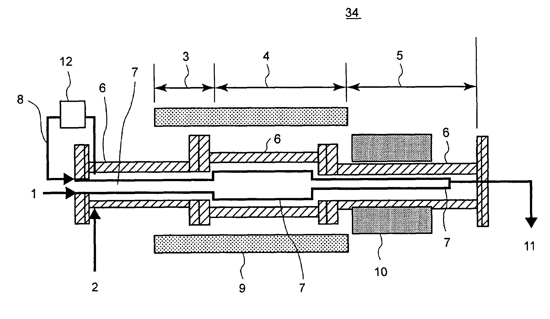
[0035]FIG. 1 shows a cross sectional view of a reaction vessel 34 installed in a treatment apparatus for organic waste according to this embodiment. Namely, in the treatment apparatus for continuously feeding and continuously pulling out a fluid to be treated including waste 1 and water or hydrogen peroxide water 2 to and from the reaction vessel 34 held in an atmosphere above the critical point of water, the reaction vessel 34 is a double vessel composed of an external vessel 6 and an internal vessel 7. The internal vessel 7 and the external vessel 6 are interconnected via an interconnection pipe 8 installed outside the external vessel 6, and thereby the internal pressure of the internal vessel 7 is practically equal to the internal pressure of the external vessel 6.

[0036]In FIG. 1, waste 1 is fed to the internal vessel 7 of the reaction vessel 34, and water or hydrogen peroxide w...

embodiment 2

[0047]Next, a treatment apparatus for organic waste according to a second embodiment of this invention will be explained. In the reaction vessel 34 shown in FIG. 1 or 2, when the internal vessel 7 is made of titanium, tantalum, or titanium palladium, organic waste which generates a corrosive acid such as sulfuric acid by decomposition can be treated.

[0048]FIG. 4 shows measured results of the corrosion rate of titanium (Ti), tantalum (Ta), and titanium palladium (Ti—Pd) along with stainless steel 316L, Inconel 625, and Hastelloy C-276 for comparison. Test specimens are dipped in a case (a) 2% hydrogen peroxide water +2% sulfuric acid or in a case (b) 2% hydrogen peroxide water +2% hydrochloric acid for five hours, and weight change amounts are measured. The temperature and pressure conditions are 400° C. and 28.5 MPa in two cases (a) and (b). The test results show that stainless steel 316L, Inconel 625, and Hastelloy C-276 greatly reduce in weight and corrode remarkably. While titani...

embodiment 3

[0052]Next, a treatment apparatus for organic waste according to a third embodiment of the present invention will be explained by referring to FIGS. 5, 6, and 7. FIG. 5 is a cross sectional view of the entrance of the reaction vessel 34 according to this embodiment. The entrance of the reaction vessel 34 is structured so as to fix the internal vessel 7 to the external vessel 6. With a fixed part 13 as a start point, the internal vessel 7 can freely move right and left in correspondence with up and down of the temperature. For a feed pipe 14 of the waste 1, at the entrance of the reaction vessel 34, a pipe 15 (for example, stainless steel) intensive at high temperature is used and in the internal vessel 7, a corrosion-resistant pipe (for example, titanium) is used.

[0053]The waste 1 is introduced from the feed pipe 14 into the internal vessel 7, then is heated in the heating zone 3, and reacts to water or the hydrogen peroxide water 2 in the reaction zone 4. On the other hand, water o...


PUM

PropertyMeasurementUnit
critical pointaaaaaaaaaa
pressureaaaaaaaaaa
temperatureaaaaaaaaaa

Abstract

A treatment apparatus for organic waste including a reaction vessel for introducing and decomposing organic waste and pulling out decomposed organic waste as a treated fluid. The reaction vessel includes an internal vessel made of corrosion-resistant material, an external vessel made of pressure-resistant material provided for surrounding the internal vessel via a gap, and an interconnection pipe for interconnecting the gap and the internal vessel outside the external vessel, thereby to control inside the gap and inside the internal vessel to practically equal pressure. The internal vessel has a heating zone for heating the introduced organic waste to a temperature higher than a critical point of water, a reaction zone for holding and decomposing the organic waste at a temperature higher than the critical point of water, and a cooling zone for cooling the treated fluid containing a decomposition product of the organic waste to lower than 100° C. The gap is adapted to be charged with high-pressure water or hydrogen peroxide water.

Description

CROSS-REFERENCE TO RELATED APPLICATIONS[0001]This application is based upon and claims the benefit of priority from the prior Japanese Patent Application No. 2003-295480, filed on Aug. 19, 2003; the entire contents of which are incorporated herein by reference.BACKGROUND OF THE INVENTION[0002]1. Field of the Invention[0003]The present invention relates to a treatment apparatus and a treatment method for organic waste for safely and continuously decomposing organic waste containing polybiphenyl chloride (PCB), polyvinyl chloride, or radioactive substances etc.[0004]2. Description of the Background[0005]In recent years, in relation to the earth environmental problems, treatment of organic waste including harmful substances such as polybiphenyl chloride (PCB), decomposition retardant substances such as fron gas, resin such as polyvinyl chloride, or radioactive substances is a big problem. Generally, organic waste is treated by the incineration. However, by this incineration treatment m...

Claims


Application Information

Patent Timeline
Patent Type & Authority Patents(United States)
IPC IPC(8): B01J8/02A62D3/20A62D101/22B01D53/68B01D53/78B01J3/00B01J3/02B01J3/04C07B35/06C07B37/06F28D21/00G21F9/00G21F9/06G21F9/30
CPCB01J3/008G21F9/04
Inventor AKAI, YOSHIEOOSAKI, MASAHIKOYAMADA, KAZUYATAKADA, TAKAO
Owner KK TOSHIBA
Why Eureka
Try Eureka