Resonant ellipsometer and method for determining ellipsometric parameters of a surface

a technology of ellipsometric parameters and ellipsometric measurement, which is applied in the field of ellipsometric optical measurement systems, can solve the problems of limited system resolution of standard ellipsometers, and achieve the effect of complex optical surface characteristic measurement capabilities and improved performance of ellipsometers

Inactive Publication Date: 2008-02-12
XYRATEX TECH LTD
View PDF15 Cites 14 Cited by
  • Summary
  • Abstract
  • Description
  • Claims
  • Application Information

AI Technical Summary

Benefits of technology

[0012]The above objectives of improving the performance of ellipsometers as well as adding complex optical surface characteristic measurement capabilities to resonator-based optical systems is achieved in a method and apparatus that incorporate a resonator having intra-resonator reflections that include a surface of interest for measurement or detection purposes. The angle of incidence of the intersection of the intra-resonator reflections with the surface of interest is an angle away from normal, so that polarization changes due to the reflection (including transmission and absorption effects on the reflections) can be measured, and specifically, the ellipsometric parameters, i.e. the complex reflectivity for each of a set of orthogonal polarizations can be measured on the surface of interest. The system can also serve as a polarimeter that yields only the relative magnitude of the reflectivities.

Problems solved by technology

However, standard ellipsometers are limited by the resolution of the system, the phase sensitivity of an interferometric measurement and / or the accuracy of the amplitude-based “manual” ellipse technique described above.

Method used


Image

  • Resonant ellipsometer and method for determining ellipsometric parameters of a surface
  • Resonant ellipsometer and method for determining ellipsometric parameters of a surface
  • Resonant ellipsometer and method for determining ellipsometric parameters of a surface

Examples


Embodiment Construction

[0023]The above-incorporated patent applications describe various resonator-enhanced optical systems, such as optical storage data and retrieval systems having improved data density, optical measurement systems having improved resolution and contrast, and optical systems having improved detector phase / amplitude slope characteristics controlled over portions of the detector response. The above-recited improvements are developed by placement and tuning of resonators within the optical paths of the associated systems.

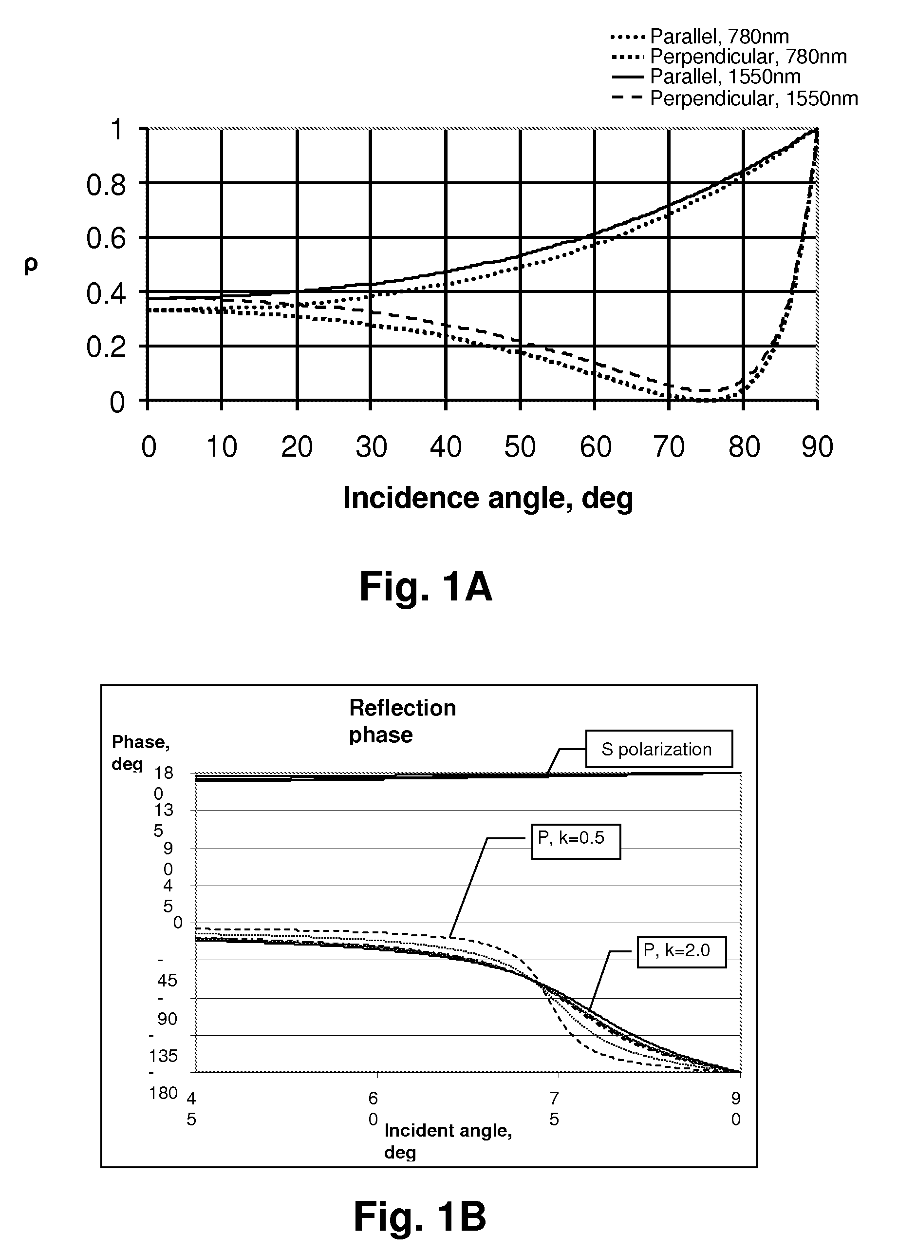
[0024]When a Fabry-Perot interferometer is adjusted to form an optical resonator, the illumination direction is typically oriented along a direction normal to the two mirrors. Therefore the incidence angle is normal and polarization does not affect the reflectivity, as no polarization change occurs on reflection at normal incidence. The only factor influencing the reflectivity remains the refractive index (the same for both polarizations unless the material is bi-refringen...


PUM

PropertyMeasurementUnit
refractive indexaaaaaaaaaa
incidence angleaaaaaaaaaa

Abstract

A resonant ellipsometer and method for determining ellipsometric parameters of a surface provide an efficient and low-cost mechanism for performing ellipsometric measurements. A surface of interest is included as a reflection point of a resonance optical path within a resonator. The intersection of the resonance optical path with the surface of interest is at an angle away from normal so that the complex reflectivity of the surface alters the phase of the resonance optical path. Intensity measurements of light emitted from a partially reflective surface of the resonator for orthogonal polarizations and for at least two effective cavity lengths provide complete information for computing the ellipsoidal parameters on the surface of interest. The resonator may be a Fabry-Perot resonator or a ring resonator. The wavelength of the illumination can be swept, or the cavity length mechanically or electronically altered to change the cavity length.

Description

CROSS-REFERENCE TO RELATED APPLICATIONS[0001]This application is related to U.S. Provisional Patent Applications: “Polarization-Enhanced Fabry Perot Detection”, Ser. No. 60 / 581,506 and “Ellipsometric Optical Resonators and Ellipso-Height Topography”, Ser. No. 60 / 583,342 filed by the same inventors on Jun. 21, 2004 and Jun. 28, 2004, respectively, from which benefit under 35 U.S.C. §119(e) is claimed. The present application is also a Continuation-in-Part of U.S. patent application Ser. No. 10 / 644,243 issued as U.S. Pat. No. 7,022,978 on Apr. 4, 2006, entitled “METHOD AND APPARATUS INCLUDING IN-RESONATOR IMAGING LENS FOR IMPROVING RESOLUTION OF A RESONATOR-ENHANCED OPTICAL SYSTEM”, which was filed on Aug. 20, 2003 having at least one common inventor and assigned to the same assignee, the specification of which is incorporated by reference. The present application is also related to U.S. patent applications: Ser. No. 11 / 143,018 entitled “FABRY-PEROT RESONATOR APPARATUS AND METHOD FOR ...

Claims


Application Information

Patent Timeline
Patent Type & Authority Patents(United States)
IPC IPC(8): G01B9/02G01J4/00G01N21/21
CPCG01N21/211
Inventor BRUNFELD, ANDREITOKER, GREGORYCLARK, BRYAN
Owner XYRATEX TECH LTD
Why Eureka
Try Eureka