Fiber-optic dissolution systems devices, and methods

a fiber-optic and system device technology, applied in the field of fiber-optic dissolution systems devices and methods, can solve the problems of current fiber-optic techniques, inaccurate data production, and turbulence in the dissolution media of fiber-optic probes

Inactive Publication Date: 2008-02-19
AGILENT TECH INC
View PDF22 Cites 7 Cited by
  • Summary
  • Abstract
  • Description
  • Claims
  • Application Information

AI Technical Summary

Benefits of technology

[0031]The present invention is adapted most advantageously for use in connection with the dissolution test vessels of dissolution media preparation/testing equipment and sample analyzing instruments. However, as the various features and functions of the invention are described herein, it will become evident that the invention finds utility in various sample measurement processes and thus is not restricted to dissolution-related processes. The invention provides remote, non-resident flow-through cells for the measurement of samples of media (e.g., dissolution media) taken from the test vessels. The media are removed from the dissolution vessel, preferably using a filter (for example, a 10-micron filter) and a pump, and then sent to the flow cell where the fiber optic probe or other type of fiber-optic device resides

Problems solved by technology

Unfortunately, particulates in the media tend to interfere with the UV scan and consequently produce inaccurate data.
Moreover, fiber-optic probes induce turbulence in the dissolution media.
Current fiber-optic techniques are also disadvantageous in that they require calibration prior to each test run.
Such analytical errors can result from operator errors, programming errors, equipment malfunctions, contamination, clogging, media loss, and so on.
M

Method used


Image

  • Fiber-optic dissolution systems devices, and methods
  • Fiber-optic dissolution systems devices, and methods
  • Fiber-optic dissolution systems devices, and methods

Examples


Embodiment Construction

[0051]In general, the term “communicate” (e.g., a first component “communicates with” or “is in communication with” a second component) is used herein to indicate a structural, functional, mechanical, optical, or fluidic relationship between two or more components or elements. As such, the fact that one component is said to communicate with a second component is not intended to exclude the possibility that additional components may be present between, and / or operatively associated or engaged with, the first and second components.

[0052]As used herein, the terms “beam,”“pulse,” and “optical signal” are intended to be interchangeable to indicate that the present invention is applicable to the transmission of light energy by both continuous and non-continuous methods.

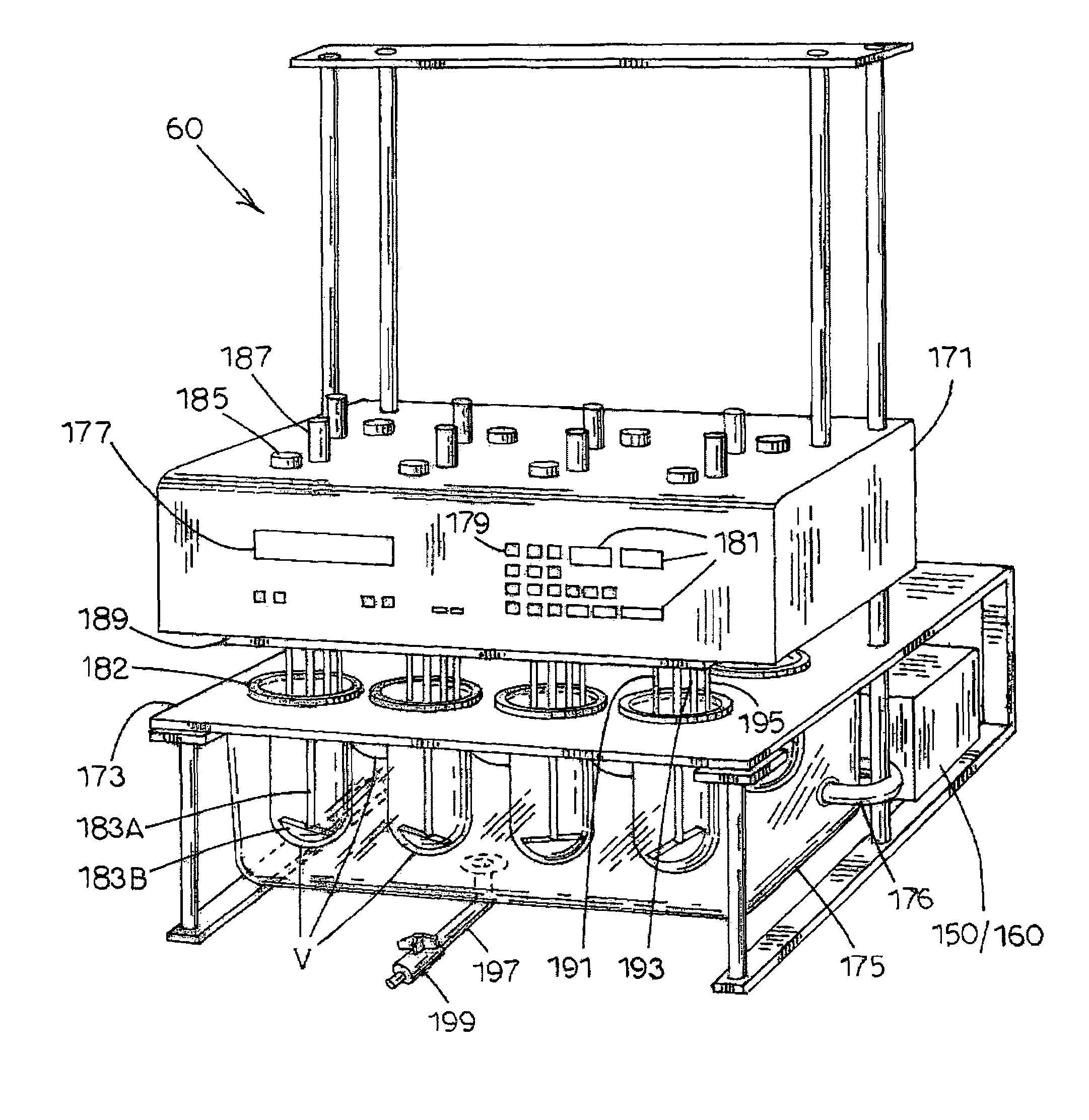
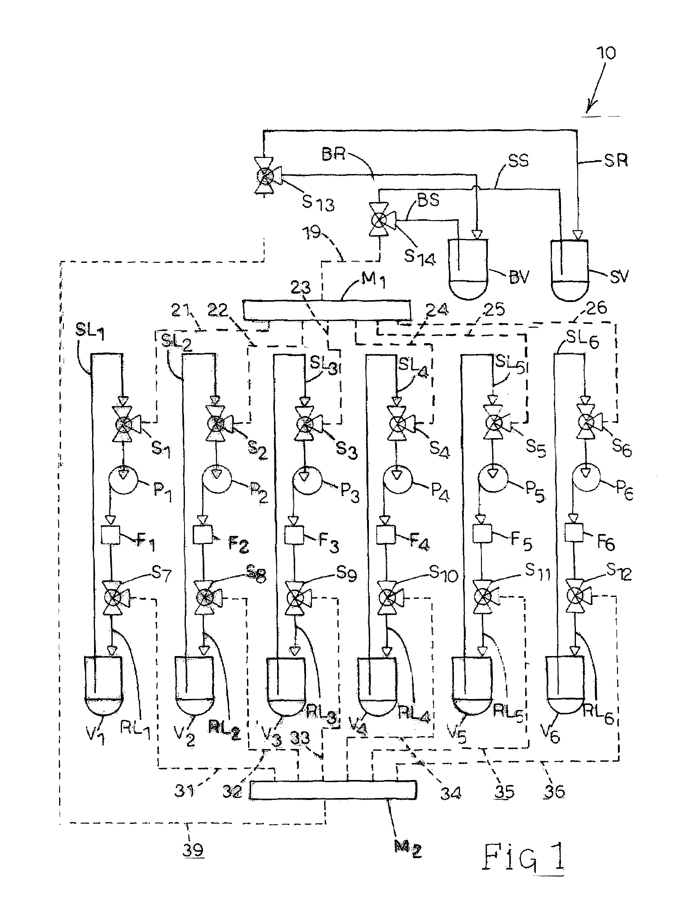
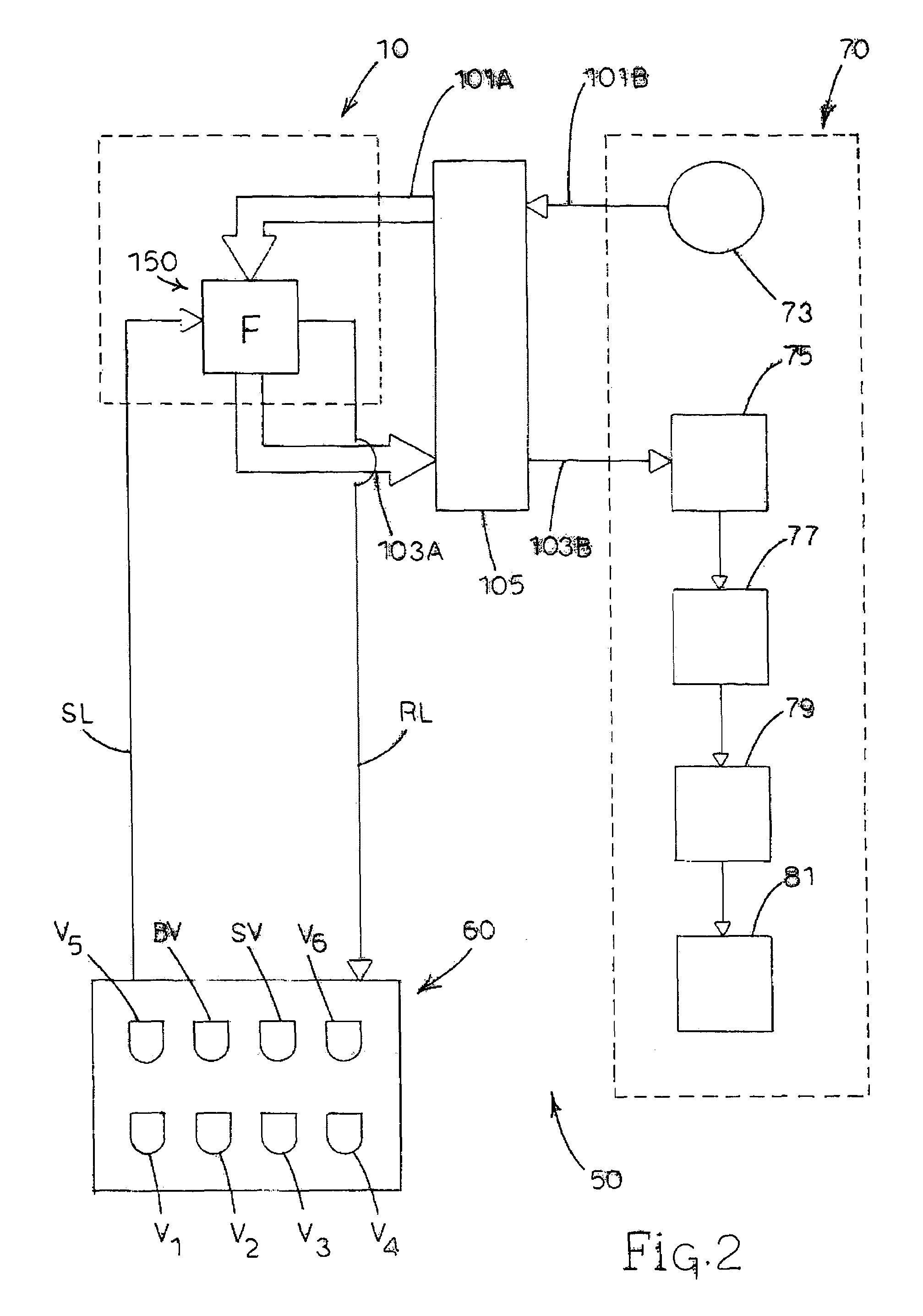
[0053]Referring now to FIG. 1, a dissolution media sampling system, generally designated 10, is illustrated in accordance with the present invention. Sampling system 10 includes a plurality of (e.g., six) test vessels V1-V6...


PUM


Abstract

A dissolution system provides remote flow cells integrated into a manifold device. The manifold device communicates with liquid input and output lines associated with each flow cell, as well as fiber-optic input and output lines associated with each flow cell. Liquid samples are respectively drawn from dissolution vessels, optically-related measurements are taken, and the samples are thereafter returned their respective vessels. The manifold device can be adapted to receive probe-type instruments that incorporate the fiber-optics, wherein each probe-type instrument is associated with each flow cell. Alternatively, each corresponding pair of fiber-optic input and output lines are disposed in opposing, optically-aligned relation and probe-type instruments are not used. The gap between the ends of the opposing fiber-optic lines provides a light path across the corresponding flow cell. Calibration procedures using blank and/or standard media are performed using the same flow cells, with provisions made for bypassing the vessels in which the samples to be analyzed are held.

Description

RELATED APPLICATIONS[0001]This application is a continuation of U.S. patent application Ser. No. 10 / 014,270 filed on Nov. 7, 2001 now U.S. Pat. No. 6,764,651 and titled “FIBER-OPTIC DISSOLUTION SYSTEMS, DEVICES, AND METHODS”, which is incorporated in its entirety in this application by reference.FIELD OF THE INVENTION[0002]The present invention relates generally to the preparation, sampling and analyzing of soluble materials. More particularly, the present invention relates to apparatus and methods for implementing flow-through techniques and the use of fiber optics in connection with the testing of soluble materials.BACKGROUND OF THE INVENTION[0003]Dissolution testing is often performed as part of preparing and evaluating soluble materials such as pharmaceutical dosage forms (e.g., tablets consisting of a therapeutically effective amount of active drug carried by an excipient material). Typically, dosage forms are dropped into test vessels that contain dissolution media of a predet...

Claims


Application Information

Patent Timeline
IPC IPC(8): G01N21/00G01N1/00G01N13/00G01N21/11G01N21/25G01N21/27G01N21/33G01N33/15
CPCG01N13/00G01N21/253G01N21/8507G01N33/15Y10T436/2575G01N2021/8521G01N2021/8528Y10T436/117497G01N2013/006
Inventor FERNANDO, C. J. ANTHONYSWON, JAMES E.HOFER, HENRY Z.
Owner AGILENT TECH INC
Why Eureka
Try Eureka