Methods of fabricating microneedle arrays using sacrificial molds, and microneedle arrays fabricated thereby

a technology of sacrificial molds and microneedle arrays, applied in the field of hypodermic needles, can solve the problems of large diameter damage to biological tissue during penetration, and the pain of tissue penetration, and achieve the effect of low cost and low cos

Inactive Publication Date: 2008-02-19
MEMSCAP
View PDF14 Cites 44 Cited by
  • Summary
  • Abstract
  • Description
  • Claims
  • Application Information

AI Technical Summary

Benefits of technology

[0006]The present invention provides methods of fabricating microneedle arrays by providing a sacrificial mold including a substrate and an array of posts, preferably solid posts, projecting therefrom. A first material is coated on the sacrificial mold including on the substrate and on the array of posts. The sacrificial mold is removed to provide an array of hollow tubes projecting from a base. The outer surfaces, and preferably the in...

Problems solved by technology

Unfortunately, the large diameter can damage biological tissue during penetration.
Moreover, tissue penetration often is painful due to the relatively large needle diameter.
Unfortunately, notwithstanding the applicability of microelectronic fabrication techniques to the fabricati...

Method used


Image

  • Methods of fabricating microneedle arrays using sacrificial molds, and microneedle arrays fabricated thereby
  • Methods of fabricating microneedle arrays using sacrificial molds, and microneedle arrays fabricated thereby
  • Methods of fabricating microneedle arrays using sacrificial molds, and microneedle arrays fabricated thereby

Examples


Embodiment Construction

[0022]The present invention now will be described more fully hereinafter with reference to the accompanying drawings, in which preferred embodiments of the invention are shown. This invention may, however, be embodied in many different forms and should not be construed as limited to the embodiments set forth herein; rather, these embodiments are provided so that this disclosure will be thorough and complete, and will fully convey the scope of the invention to those skilled in the art. In the drawings, the thickness of layers and regions are exaggerated for clarity. Like numbers refer to like elements throughout. It will be understood that when an element such as a layer, region or substrate is referred to as being “on” another element, it can be directly on the other element or intervening elements may also be present. In contrast, when an element is referred to as being “directly on” another element, there are no intervening elements present.

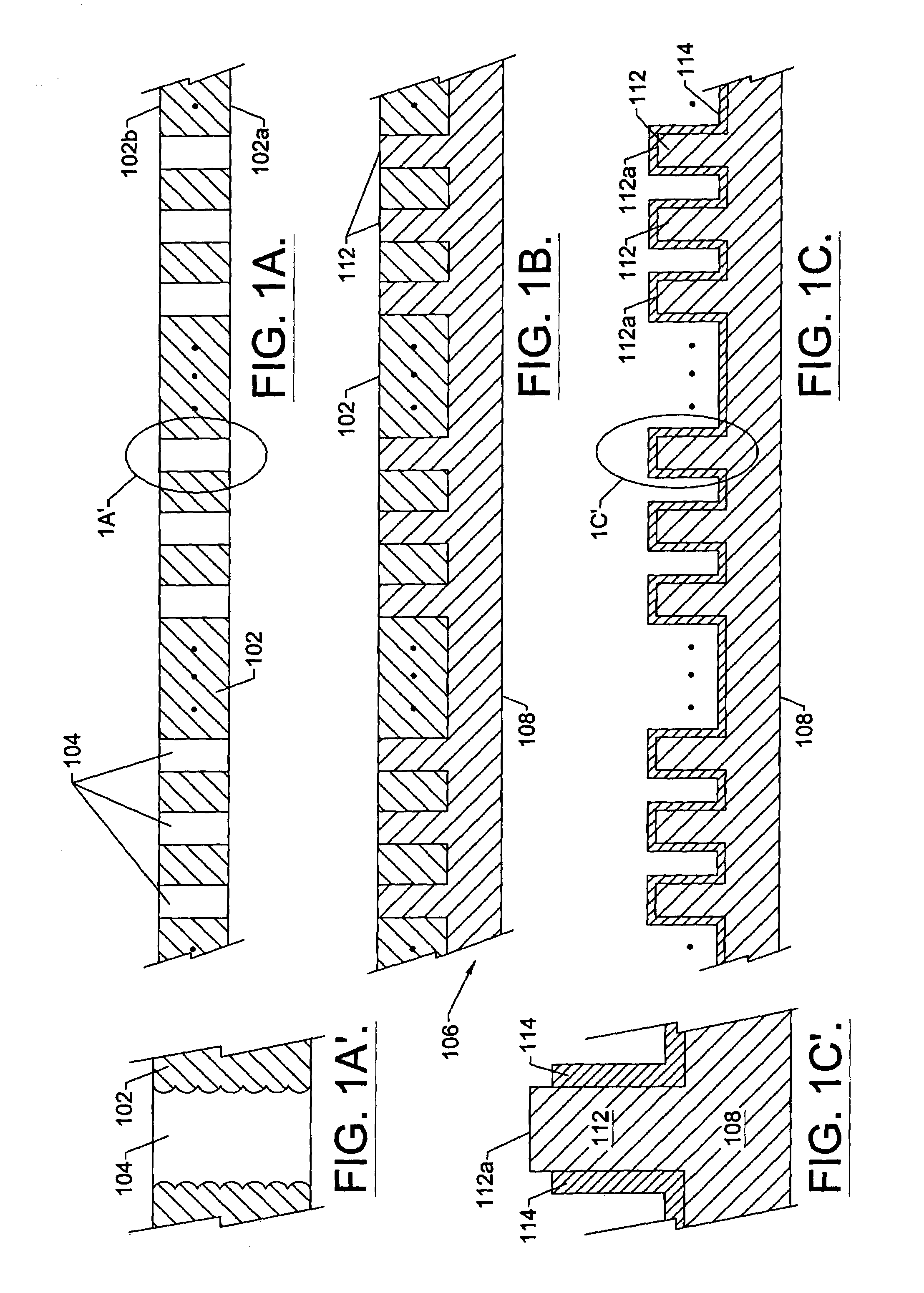
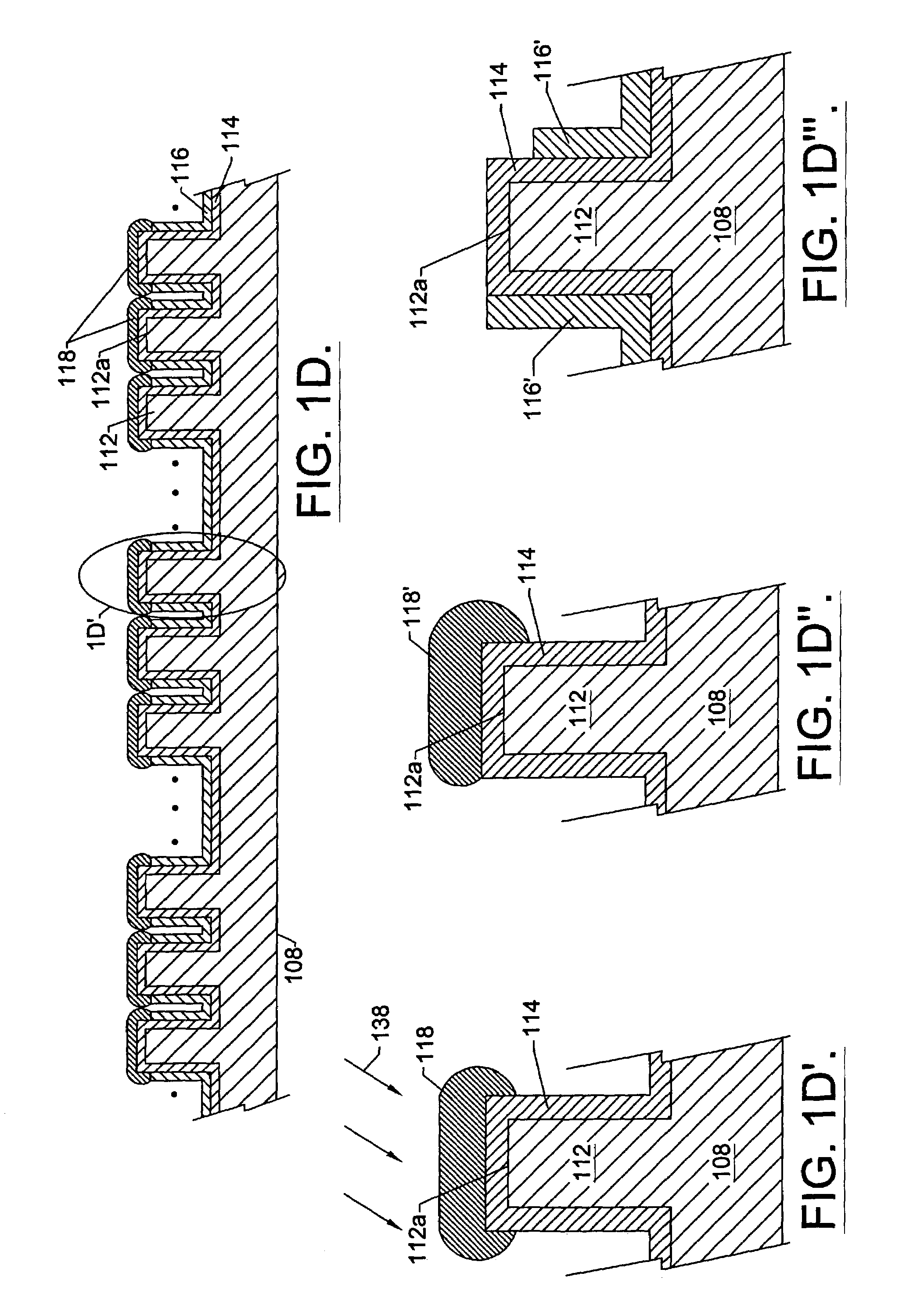
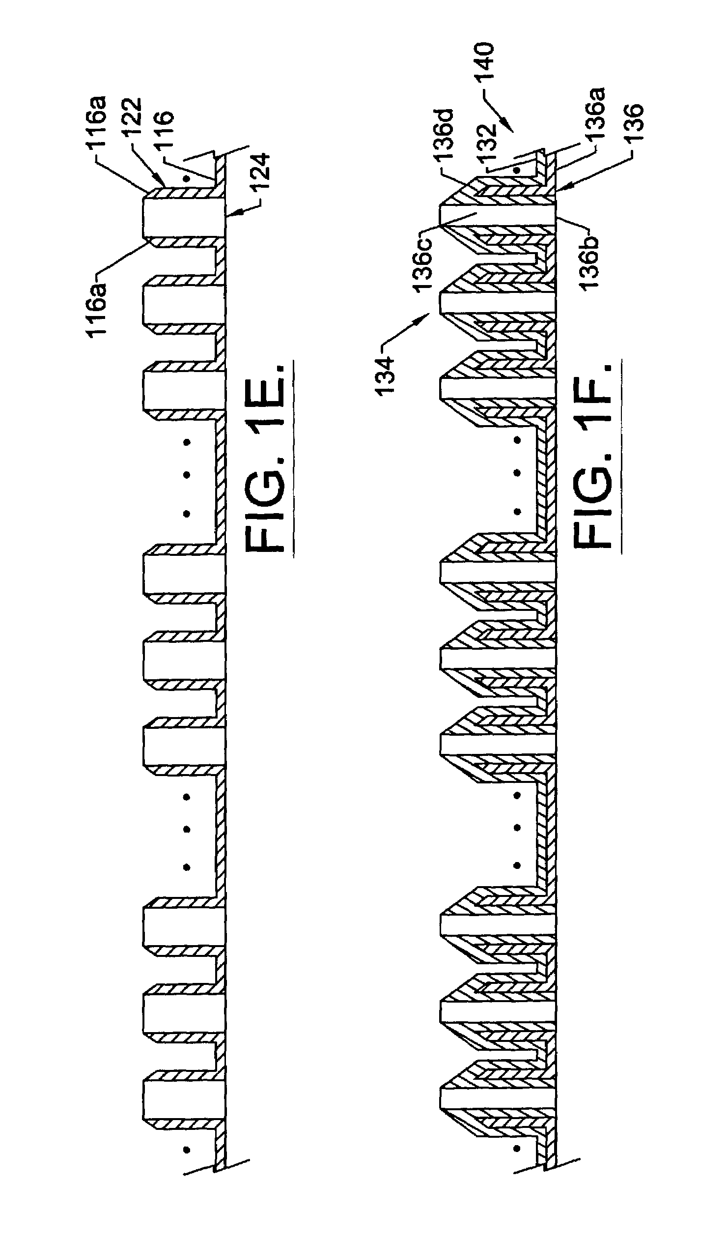
[0023]FIGS. 1A-1F are cross-sectional vi...


PUM


Abstract

Microneedle arrays are fabricated by providing a sacrificial mold including a substrate and an array of posts, preferably solid posts, projecting therefrom. A first material is coated on the sacrificial mold including on the substrate and on the array of posts. The sacrificial mold is removed to provide an array of hollow tubes projecting from a base. The inner and outer surfaces of the array of hollow tubes are coated with a second material to create the array of microneedles projecting from the base. The sacrificial mold may be fabricated by fabricating a master mold, including an array of channels that extend into the master mold from a face thereof. A third material is molded into the channels and on the face of the master mold, to create the sacrificial mold. The sacrificial mold then is separated from the master mold. Alternatively, wire bonding may be used to wire bond an array of wires to a substrate to create the sacrificial mold. The first material preferably is coated on the sacrificial mold by plating. Prior to plating, a plating base preferably is formed on the sacrificial mold including on the substrate and on the array of posts. The inner and outer surfaces of the array of hollow tubes preferably are coated with the second material by overplating the second material on the inner and outer surfaces of the array of hollow tubes.

Description

CROSS-REFERENCE TO RELATED APPLICATION[0001]This application is a divisional of application Ser. No. 09 / 442,827, filed Nov. 18, 1999 (now U.S. Pat. No. 6,511,463), entitled Methods of Fabricating Microneedle Arrays Using Sacrificial Molds, assigned to the assignee of the present application, the disclosure of which is hereby incorporated herein by reference in its entirety as if set forth fully herein.FIELD OF THE INVENTION[0002]This invention relates to hypodermic needles, and more particularly to microneedles and fabrication methods thereof.BACKGROUND OF THE INVENTION[0003]Hypodermic needles are widely used in the biomedical field for injection into and extraction from living tissue. Hypodermic needles generally have a relatively large diameter, for example on the order of millimeters. Unfortunately, the large diameter can damage biological tissue during penetration. Moreover, tissue penetration often is painful due to the relatively large needle diameter.[0004]Accordingly, micron...

Claims


Application Information

Patent Timeline
IPC IPC(8): B05D7/22B05D1/36A61B5/15A61M37/00B81C99/00
CPCA61B5/1411A61M37/0015B81C99/0085A61B5/14514A61M2037/003A61M2037/0053Y10T29/49222Y10T29/302B81B2201/055A61B5/150022A61B5/150282A61B5/150984
Inventor WOOD, ROBERT L.WYNANDS, HENRY A.MARKUS, KAREN W.
Owner MEMSCAP
Why Eureka
Try Eureka