Reconfigurable, multi-user communications network, with low latency time

Active Publication Date: 2008-02-19
RADIALL SA
View PDF12 Cites 5 Cited by
  • Summary
  • Abstract
  • Description
  • Claims
  • Application Information

AI Technical Summary

Benefits of technology

[0006]The proposed invention consists of reconfigurable, multi-user optical communications network, with low latency time based on the use of modulation of the optical power of a emission source

Problems solved by technology

However, the high reconfiguration time (from several hundred microseconds to several milliseconds) makes this system unsuitable for datacom applications.
However, the disadvantage of t

Method used


Image

  • Reconfigurable, multi-user communications network, with low latency time
  • Reconfigurable, multi-user communications network, with low latency time
  • Reconfigurable, multi-user communications network, with low latency time

Examples


Embodiment Construction

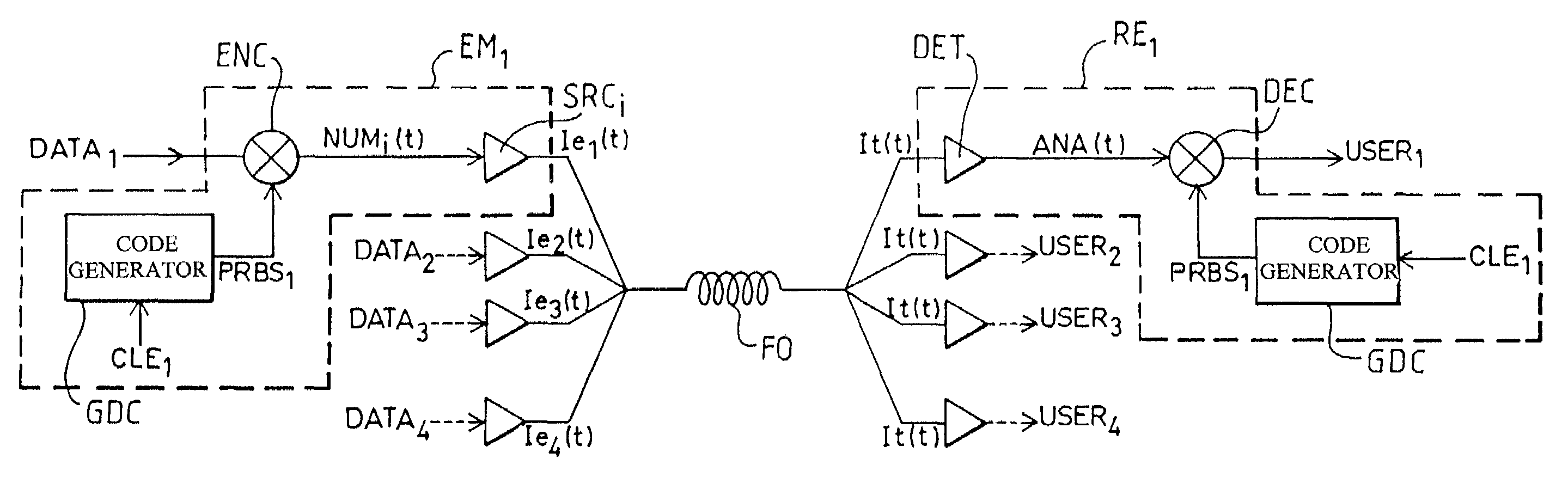
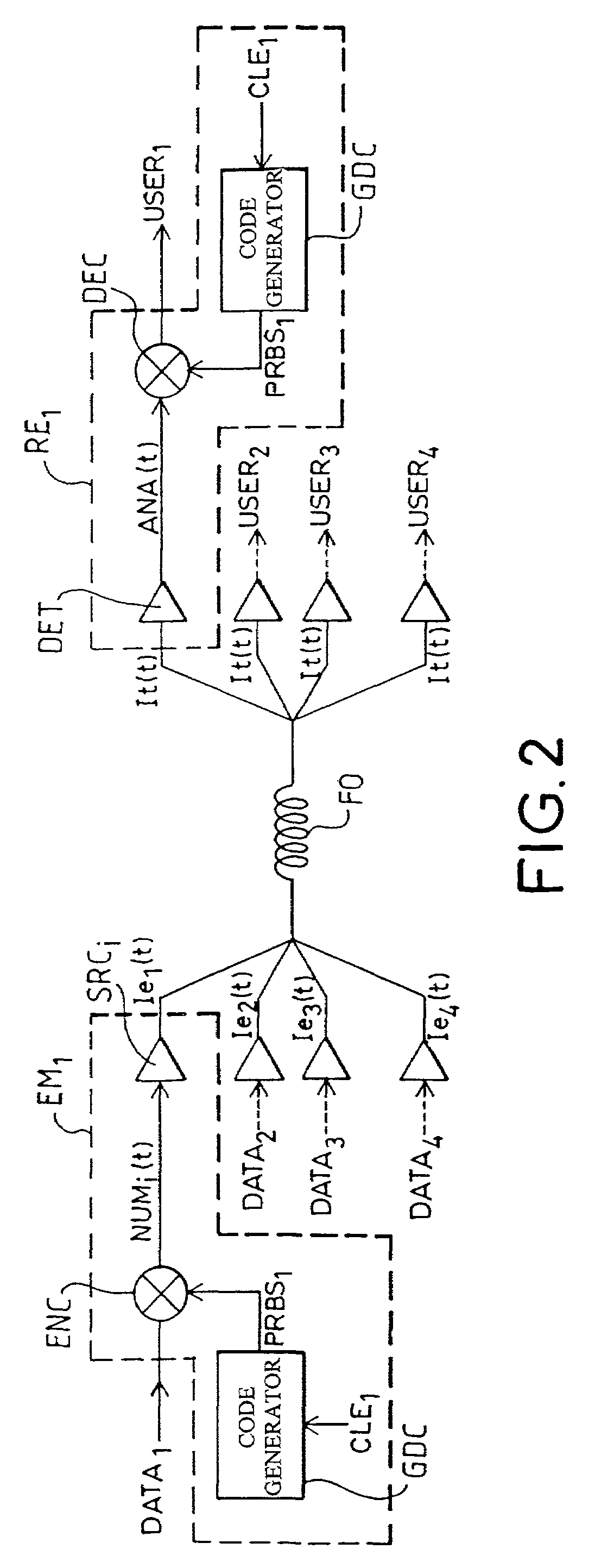
[0021]FIG. 2 describes the block diagram of the optical communications network according to the invention;

[0022]It comprises at least one transmitter EMi generating from a digital data signal DATAi a brightness-modulated light signal, optical means to transport said light signals(s) to at least one receiver REj associated with a user USERj and recreating from the light signal transmitted the data signal intended for said user. In the example of FIG. 2, the network comprises 4 transmitters and 4 receivers, index “i” referring to transmission can take values from 1 to 4 and index “j” referring to reception can also take values from 1 to 4. For clarity purposes, only transmitters and receivers EM1 and RE1 have been shown. According to the invention, each transmitter comprises a pseudo-random code generator GDC transmitting a code PRBSi generated from a predetermined software key CLEi, means ENC to encode the data signal DATAi with the code to form an encoded digital signal NUMi(t), lig...


PUM


Abstract

The invention concerns a reconfigurable, multi-user optical communications network, with low latency time.
It comprises at least one transmitter generating from a digital data signal a brightness-modulated light signal, encoded with a pseudo-random code generated from a predetermined software key, optical means to transport said light signals(s) to at least one receiver associated with a user.
Each receiver comprises direct optical detection means generating an analog electrical signal characteristic of the sum of the encoded light signals transmitted, a pseudo-random code generator identical to that of the transmitters and means to decode said analog signal using a code transmitted by said code generator with a key identical to that associated with the transmitter with which the user wants to communicate, in order to recreate the data signal intended for the user.

Description

FIELD OF THE INVENTION[0001]The invention concerns a reconfigurable, multi-user optical communications network, with low latency time, and applies more especially to datacom (data communications) applications for short distance data communications involving a small number of users.BACKGROUND OF THE INVENTION[0002]There is a vast scope for this type of network; it extends from the medical field, which has a high number of interconnections, to the aerospace field where the need for reconfiguration is of paramount importance. These networks also have numerous applications in the field of computers where the network reconfiguration times are a limiting factor as well as in the distribution of data in the radar antennas. Other examples of applications will be described below.[0003]The use of light to convey information has become more widespread since it can be used to carry a considerable amount of information. The need for reconfigurable networks makes the choice of switching element c...

Claims


Application Information

Patent Timeline
IPC IPC(8): H04J4/00H04J14/00H04B10/556H04B10/11H04B10/118H04B10/27H04B10/272H04B10/54H04J13/00H04J13/10H04J14/04H04J14/06H04K1/02
CPCH04J14/005H04K1/02H04J13/0022H04J13/10
Inventor FEZ, MATHIASBARBARY, GAELLE
Owner RADIALL SA
Why Eureka
Try Eureka