

Differential support structure, differential's component, method of manufacturing differential support structure, and method of manufacturing differential's component
a technology of differential support structure and component, which is applied in the direction of heat treatment apparatus, gearing, furnaces, etc., can solve the problems of difficult to achieve the number of grains exceeding 13 and achieve the effect of increasing life against fatigu
- Summary
- Abstract
- Description
- Claims
- Application Information
AI Technical Summary
Benefits of technology
Problems solved by technology
Method used
Image

Examples
first embodiment
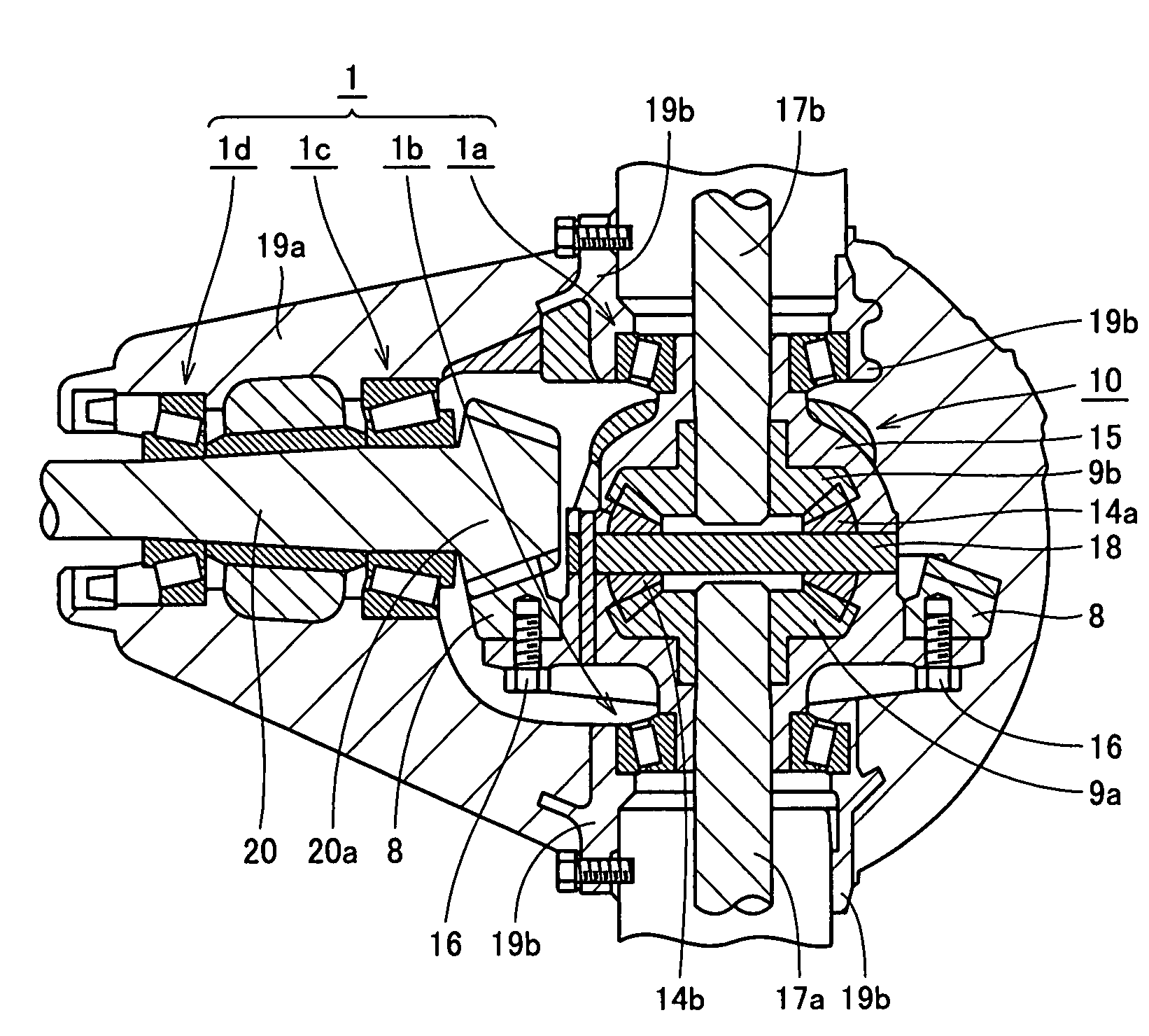
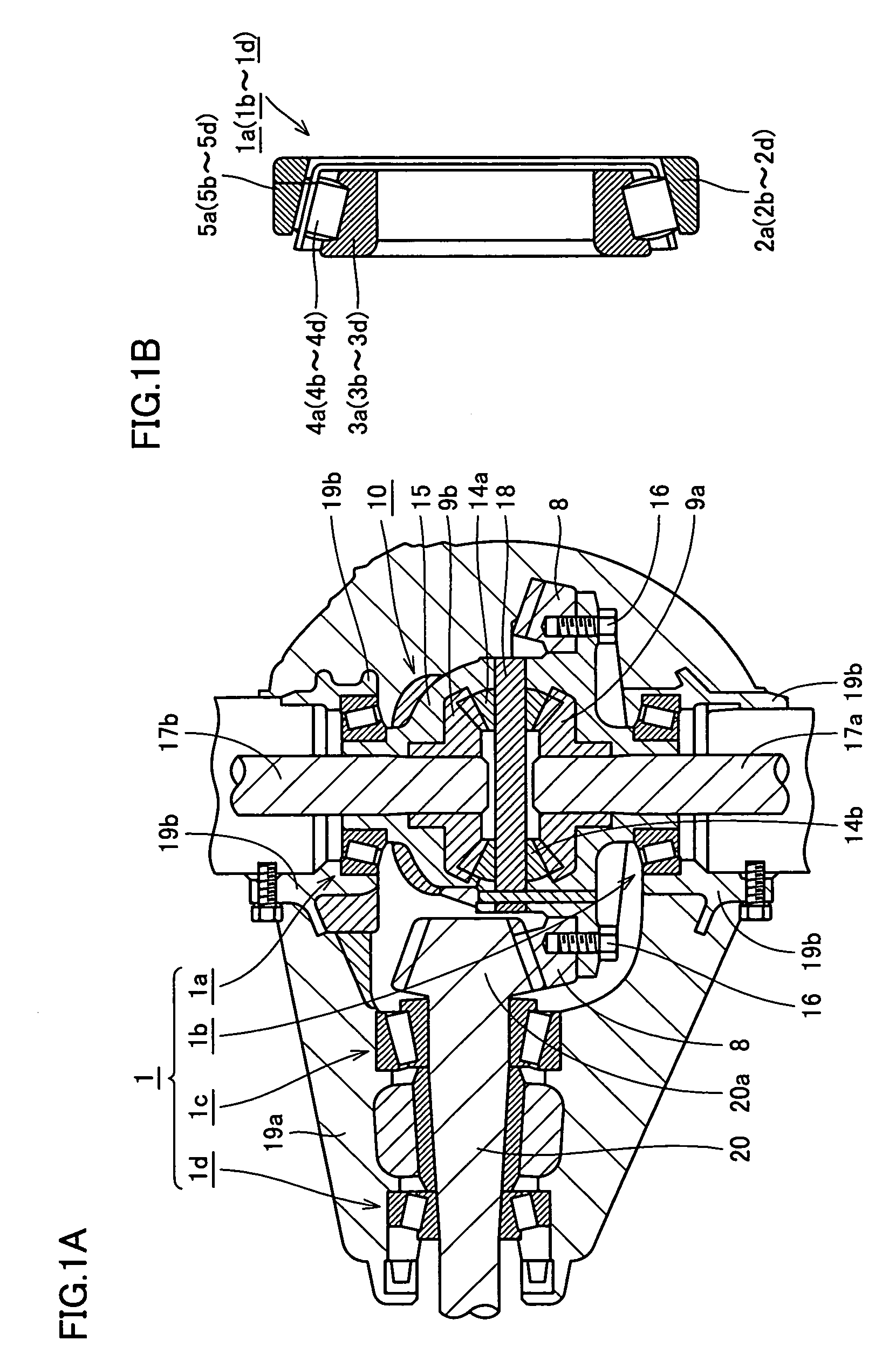
[0045]With reference to FIG. 1A, a differential 10, and external peripheral portions 19a, 19b surrounding differential 10 are shown. Differential 10 meshes with a drive pinion 20 extending leftward as seen in the figure. Drive pinion 20 rotates to transmit power to differential 10. Furthermore differential 10 has axle shafts 17a, 17b linked thereto vertically as seen in the figure. Axle shafts 17a, 17b rotate as they receive power from drive pinion 20. A differential support structure 1 supports the differential 10 drive pinion 20 and axle shafts 17a, 17b rotatably relative to external peripheral portions 19a, 19b or other similar fixed members.
[0046]Differential 10 mainly has drive pinion 20, axle shafts 17a and 17b, a pinion shaft 18, a ring gear 8, pinion gears 14a and 14b, side gears 9a and 9b, and a differential case 15. Axle shaft 17a, 17b each has an end with two wheels (not shown) connected thereto. Ring gear 8, pinion gears 14a and 14b, and side gears 9a and 9b configure a ...
second embodiment
[0066]With reference to FIG. 6, the present embodiment provides differential support structure 1 with tapered roller bearings 1a-1d replaced with deep groove ball bearings 7a-7d.
[0067]Deep groove ball bearing 7a includes an outer ring 2a, an inner ring 3a, a ball 6a, and a cage 5a. Outer ring 2a is arranged at an upper, internal peripheral surface of external peripheral portion 19b (see FIG. 1A). Inner ring 3a is arranged fitted at an upper end portion of differential 10. Ball 6a is fixed between outer ring 2a and inner ring 3a, held by cage 5a to be rolled. Deep groove ball bearing 7b includes an outer ring 2b, an inner ring 3b, a ball 6b, and a cage 5b. Outer ring 2b is arranged at a lower, internal peripheral surface of external peripheral portion 19b. Inner ring 3b is arranged fitted at a lower end portion of differential 10. Ball 6a is fixed between outer ring 2b and inner ring 3b, held by cage 5b to be rolled. Deep groove ball bearing 7c and 7d include outer rings 2c. and 2d,...
example 1
[0073]JIS-SUJ2 (1.0 wt % of C-0.25 wt % of Si-0.4 wt % of Mn-1.5 wt % of Cr) was used for Example 1 of the present invention. Samples shown in Table 1 were each produced through the procedure described below.
[0074]
TABLE 1samplesconventionallynormallycarbonitridedquenchedABCDEFproductproductsecondary7801)800815830850870——quenchingtemp. (° C.)hydrogen—0.370.400.380.420.400.720.38content(ppm)grain size no.—1211.51110101010(JIS)Charpy—6.656.406.306.206.305.336.70impact value(J / cm2)fracture—2840278026502650270023302770stress value(MPa)Rolling—5.44.23.52.92.83.11contactfatigue liferatio (L10)1)Not evaluated this time due to insufficient quenching.
Samples A-D: Examples of the Present Invention
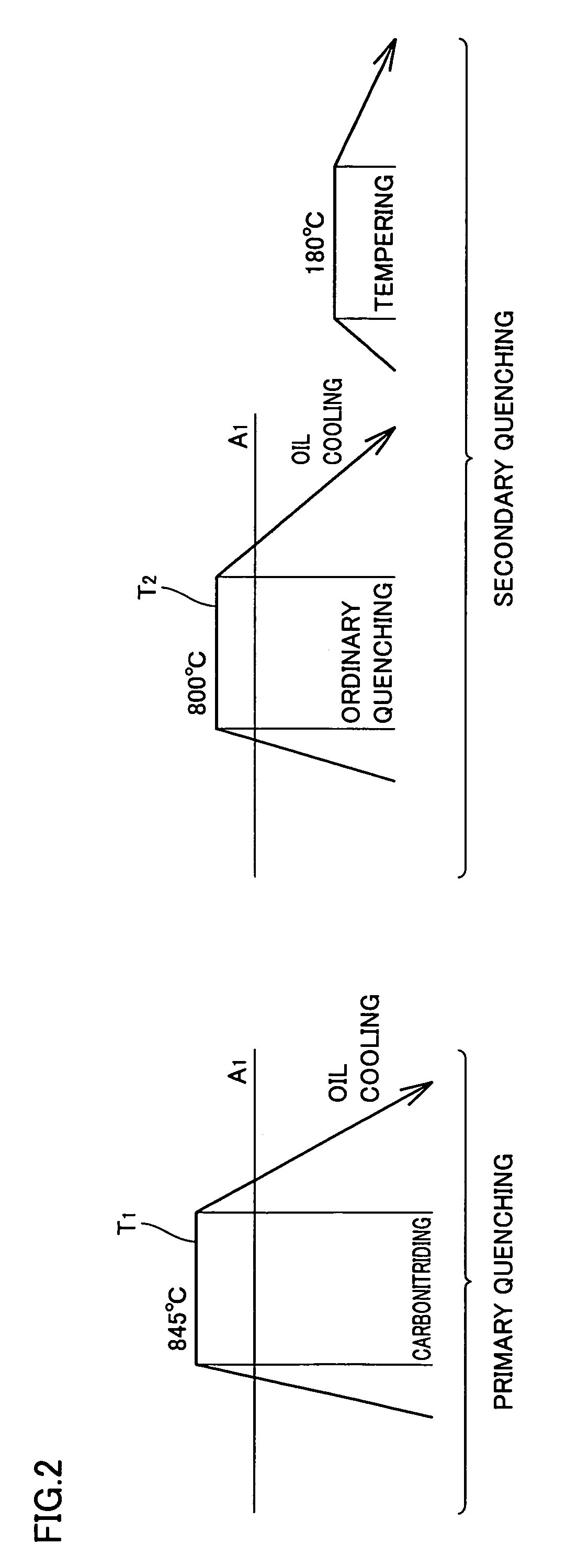
[0075]Carbonitriding was performed at 850° C. held for 150 minutes in an atmosphere of a mixture of RX gas and ammonia gas. Following the heat treatment pattern shown in FIG. 6, primary quenching was done from a carbonitriding temperature of 850° C., and secondary quenching was subsequently done by he...
PUM
| Property | Measurement | Unit |
|---|---|---|
| Temperature | aaaaa | aaaaa |
| Temperature | aaaaa | aaaaa |
| Fraction | aaaaa | aaaaa |
Abstract
Description
Claims
Application Information