Dental extra-oral x-ray imaging system and method

a x-ray imaging and extraoral technology, applied in the field of x-ray imaging devices, can solve the problems of insufficient continuous exposure, inability to see in real time, and high cost of equipment and especially the cone beam ct and transverse slicing equipment which produce multiple frames

Active Publication Date: 2008-02-26
OY AJAT LTD
View PDF15 Cites 87 Cited by
  • Summary
  • Abstract
  • Description
  • Claims
  • Application Information

AI Technical Summary

Benefits of technology

[0028]In an advantage, the system uses little no more than the radiation dose used in a regular dental panoramic exposure and performs the x-ray scan to collect such data in a continuous movement.
[0030]In another advantage, the system and method combines data from a single exposure to not only reconstruct a panoramic layer of interest but to also be able to correct part of the image that is blurred and furthermore produce transverse image slices and 3D images.

Problems solved by technology

It should be mentioned from the start that this equipment and especially the cone beam CT and transverse slicing equipment which produce multiple frames are particularly expensive being in the range of 200 kUSD to 400 kUSD (retail price).
Despite the expense, these systems are not fast enough for continuous exposure.
Consequently, real time viewing is not possible.
As can be appreciated, this is a burden that probably only large clinics can afford.
Additionally the cone beam systems require that the x-ray scan be performed for longer times and in steps (ie not continuously) because Image Intensifiers (IIs) or TFT panels are too slow and lack sensitivity.
But in each case when a new panoramic layer is needed a new exposure needs to be taken, which means additional radiation to the patient.
A disadvantage of this approach is that the movement trajectory is quite complex.
To achieve this motion, multiple motors are required (i.e. degrees of freedom) which also complicates the control electronics and algorithms, thus leading to higher cost.
In addition, one of the most severe issues experienced today in clinical applications of dental panoramic imaging is that the patient (object) does or cannot necessarily remain motionless for the whole duration of the scan (typically lasting 5 to 30 seconds).
The large-area 2D detectors are most often TFT panels and are particularly expensive because of the m / n≈1 aspect ratio (approximately equal to one).
Multiple panoramic layers, transverse slicing or 3D imaging is not possible because only a single projection is saved.
However, with current solutions, the resolution of panoramic layer calculated from the 3D data is low compared to dedicated panoramic imaging systems (OPGs).
Furthermore, the dose levels are much higher and maybe equally importantly the cost of such available systems is as mentioned in the range of 200 kUSD-400 kUSD because of the use of large and expensive flat TFT panels, expensive Image Intensifiers or simply because dental OEMs market these “advanced” systems at a price premium.
Unfortunately, such a system cannot be used in the field of dental x-ray imaging where the layer(s) of interest run around or across the human jaw.
Although such an approach may be useful in bone densitometry and in some other applications, it is, in practice, impossible to apply to dental panoramic or transverse imaging due to the fact that x-rays run essentially parallel to rather than across the layer-of-interest, should there be linear movement or rotation around the focal point.
Secondly the process disclosed in U.S. Pat. No. 6,496,557 would have another serious limitation if an attempt were to be made to apply it in the field of dental imaging.
That limitation is the most serious issue in panoramic imaging and it results in partial image blurring due to misalignment of the patient or due to patient movement.
Thirdly, U.S. Pat. No. 6,496,557 fails to address the need of a system or a procedure that is able to simultaneously perform both panoramic as well as transverse imaging.
Further, this patent fails to disclose a system operable in a dental imaging environment.
The long exposures are needed because the normally used digital imaging devices lack sensitivity and typically can “catch” only 1 out of 3 incoming x-rays.
Further, non-continuous step-wise scans are necessary in the prior art because of the slow response and slow readout of the current rectangular or square flat panel TFT arrays.
Higher doses and longer step-wise scans create higher risk and discomfort to the patient.
Additionally, the prior art does not suggest a means by which one might combine data to gain performance benefits and to correct blurring or to produce transverse image slices or even tomosynthentic 3D images.

Method used


Image

  • Dental extra-oral x-ray imaging system and method
  • Dental extra-oral x-ray imaging system and method
  • Dental extra-oral x-ray imaging system and method

Examples


Embodiment Construction

)

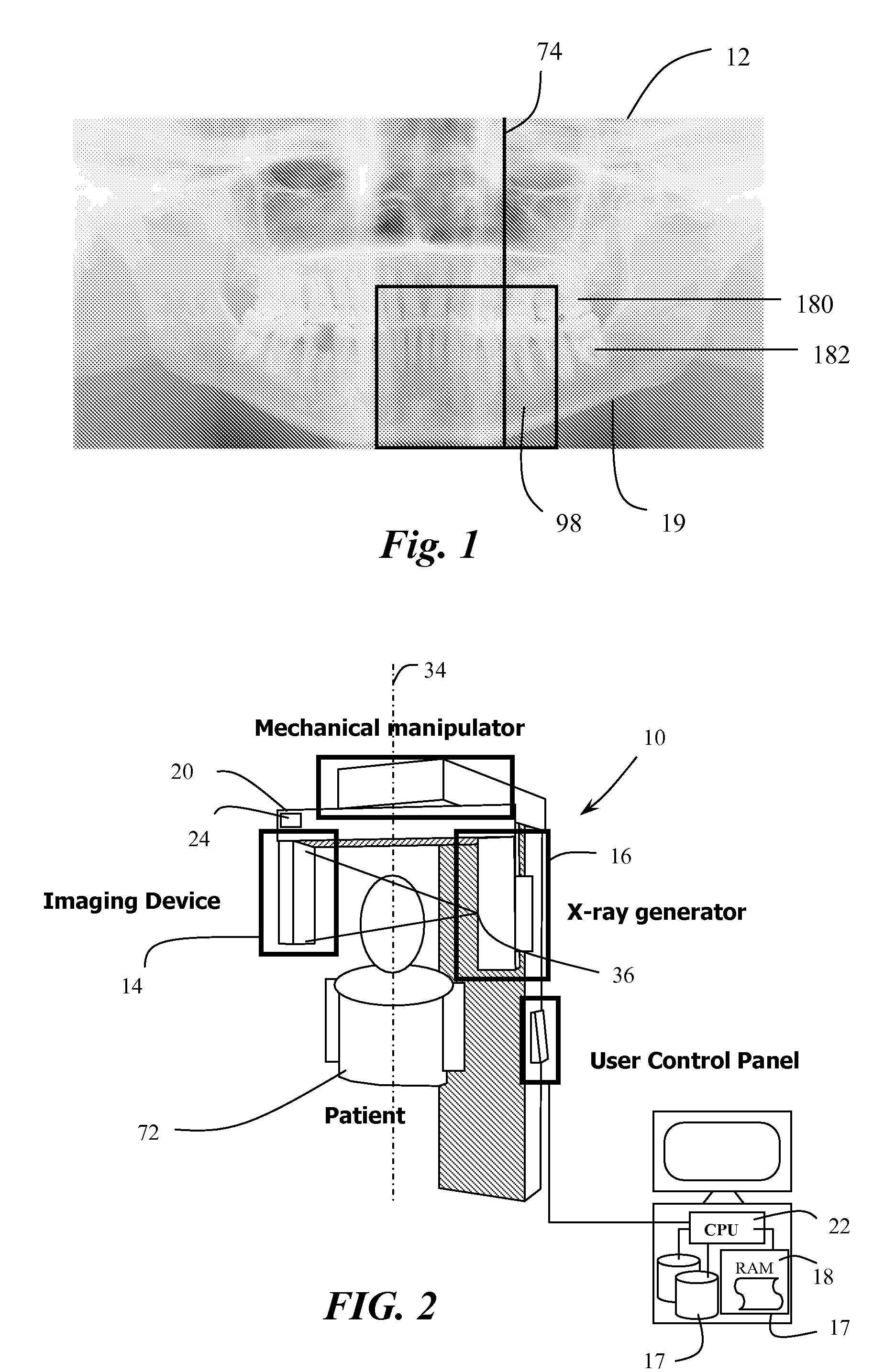
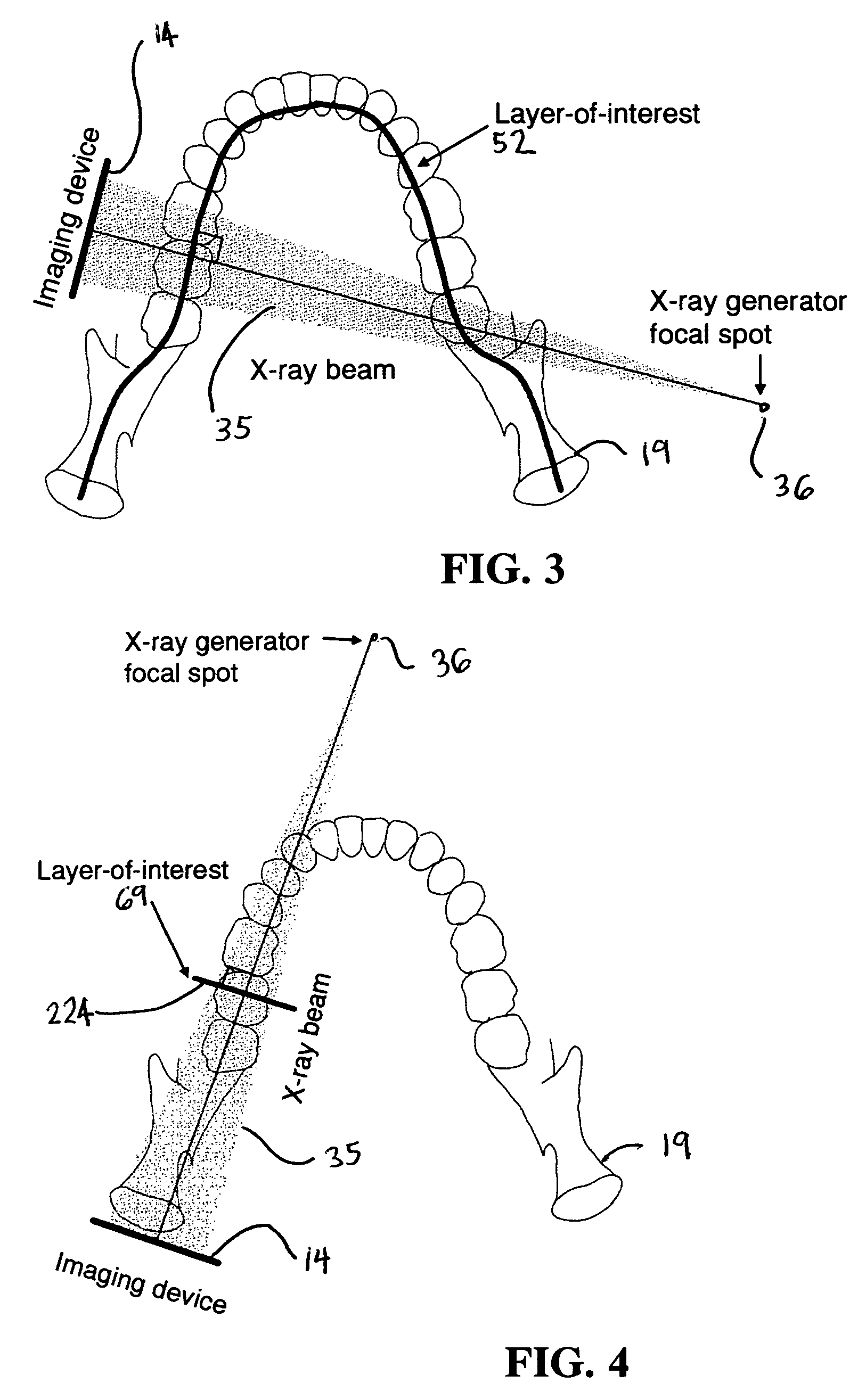
[0047]Referring now to FIGS. 1 and 2, the system 10 of the invention uses a frame mode CdTe-CMOS detectors for creating tomographic images including dental panoramic images using a dental x-ray setup. In this application, the read-out speed or frame rate need only be high enough to allow the detector to move by more than half a pixel size or preferably even less per a read-out cycle. However, serious limitations can arise such as the need to transfer a disproportionately large amount of data to a computer or the like in real-time. Therefore, it is beneficial to manage data in order to reconstruct and display an image in real-time, during the exposure.

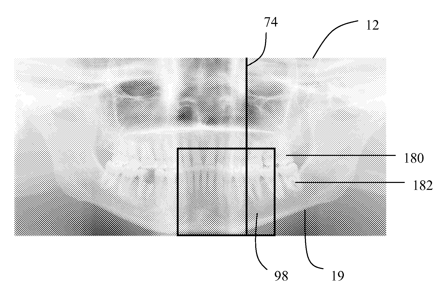
[0048]The dental x-ray imaging system 10 produces panoramic images 12 for use in dental diagnosis and treatment. The system 10, using data generated from a single exposure, selectively produces at least two of the following: 1) a predetermined dental panoramic layer image 2) at least part of another dental panoramic layer(s) 3) transve...


PUM


Abstract

A multi-layer dental panoramic and transverse x-ray imaging system includes an x-ray source; a digital imaging device capable of frame mode output with a sufficient frame rate; a mechanical manipulator having at least one rotational axis located in a position other than the focal point of the x-ray source; a position detection mechanism for detecting the camera position in 1D, 2D or 3D depending of the complexity of the trajectory; a final image reconstruction mechanism for reconstructing the final images out of the stored frames; a real time storage system such as RAM, hard drive or an drive array able to store all the frames captured during an exposure; and a digital processing unit capable of executing the reconstruction algorithm, such components being interconnected in operational arrangement. The system produces selectively dental panoramic x-ray images, dental transverse x-ray images and dental tomosynthetic 3D images from a frame stream produced by a high-speed, x-ray digital imaging device.

Description

CROSS REFERENCE TO RELATED APPLICATIONS[0001]This application claims priority to U.S. Provisional Application No. 60 / 677,020 of the same title, filed 2 May 2005, the content of which is incorporated herein by reference thereto.BACKGROUND OF THE INVENTION[0002]This invention relates to X-ray imaging devices and in particular, devices for dental extraoral X-ray imaging. Firstly, dental panoramic x-ray imaging is a well-known dental radiographic procedure. Its purpose is to produce an x-ray image of the entire jaw for diagnosis as opposed to a partial image such as obtained by intra-oral x-ray imaging. The panoramic image x-ray is particularly useful, for example, when the dentist is planning implants or surgical operations or for orthodontics procedures. A sample dental panoramic x-ray image is shown in FIG. 1. The invention relates also to other extra-oral dental x-ray imaging systems such as cone beam dental computed tomography (“CT”) system for 3-D tomosynthetic volumetric reconstr...

Claims


Application Information

Patent Timeline
Patent Type & Authority Patents(United States)
IPC IPC(8): A61B6/14G03B42/04G03B42/02
CPCA61B6/14A61B6/466A61B6/5241A61B6/547G03B42/042G06T7/0022G06T7/0065G06T7/0071H04N5/23238H04N5/32G01T1/247G06T2207/10116G06T2207/30036G06T7/55G06T7/579G06T7/97H04N23/698
Inventor SPARTIOTIS, KONSTANTINOSPANTSAR, TUOMAS
Owner OY AJAT LTD
Why Eureka
Try Eureka