
High efficiency driver for miniature loudspeakers

a miniature loudspeaker, high-efficiency technology, applied in the direction of digitally weighted transducer elements, transducer casings/cabinets/supports, electric transducers, etc., can solve the problems of short cycle of such products, limit the electrical power available to drive the miniature loudspeaker, and short design time of new products

Active Publication Date: 2008-02-26
TDK CORPARATION
View PDF18 Cites 100 Cited by
  • Summary
  • Abstract
  • Description
  • Claims
  • Application Information

AI Technical Summary

Benefits of technology

[0020]The miniature loudspeaker assembly may further comprise a control circuit, the control circuit being electrically connected between the driver and the motor. The motor may comprise a coil and a magnetic circuit. The motor may comprise a piezo element. The control circuit may be adapted to charge and to discharge...

Problems solved by technology

However, these devices are typically battery operated, which further limits the amount of electrical power available to drive the miniature loudspeaker.
Very often the life cycle of such products is very short, thus the design time of new products should be very short.
These analog class A / B amplifiers are bulky, inefficient, costly etc.
Even further, there are many constraints if one wants to standardise their usage, i.e. interface etc.
Electro-Magnetic Interference (EMI) is becoming an even more increasing problem within microelectronics, thus causing problems with poor noise performance.
Furthermore, these solutions are quite complex, and they often require many external components thus being too costly to implement in high volume low cost applications.
However, the circuit structures are rather complex, and thus not suited for low cost production.
However, it is generally known that PDM implementations require a very high clock frequency which has disadvantages such as distortion due to switching rise and fall times, and if standard components are used switching loss will result in decreased efficiency.

Method used


Image

  • High efficiency driver for miniature loudspeakers
  • High efficiency driver for miniature loudspeakers
  • High efficiency driver for miniature loudspeakers

Examples


Embodiment Construction

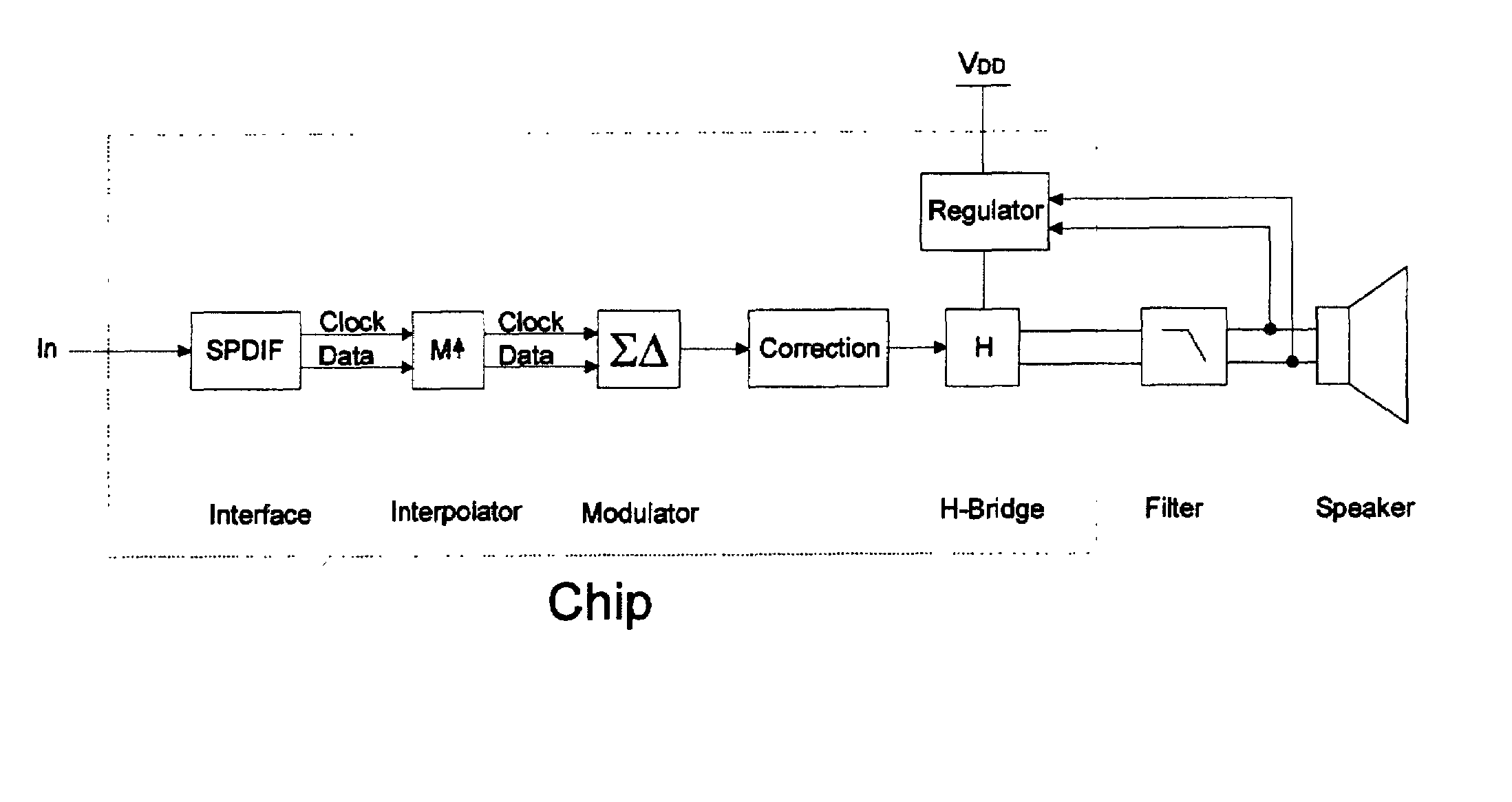
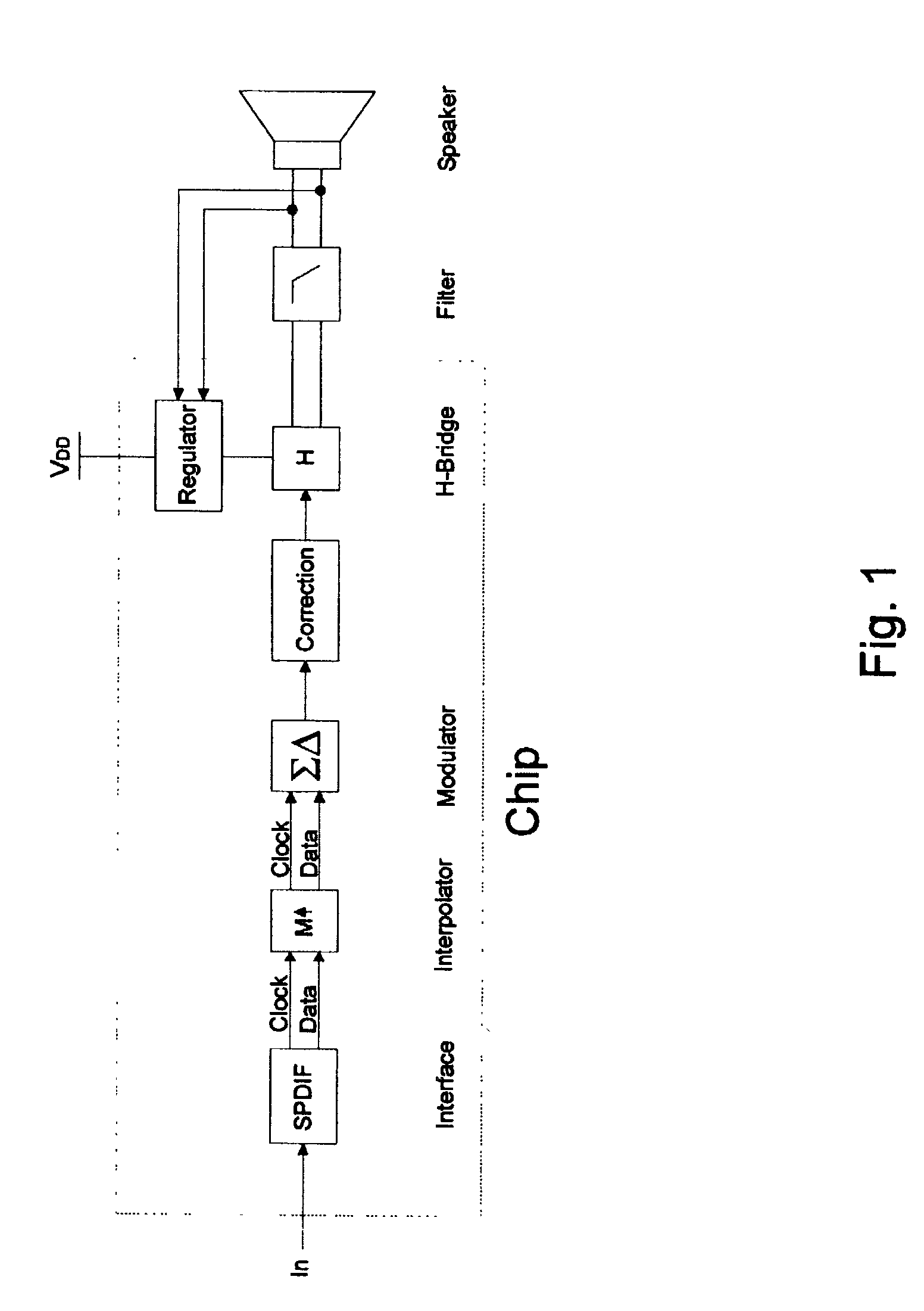
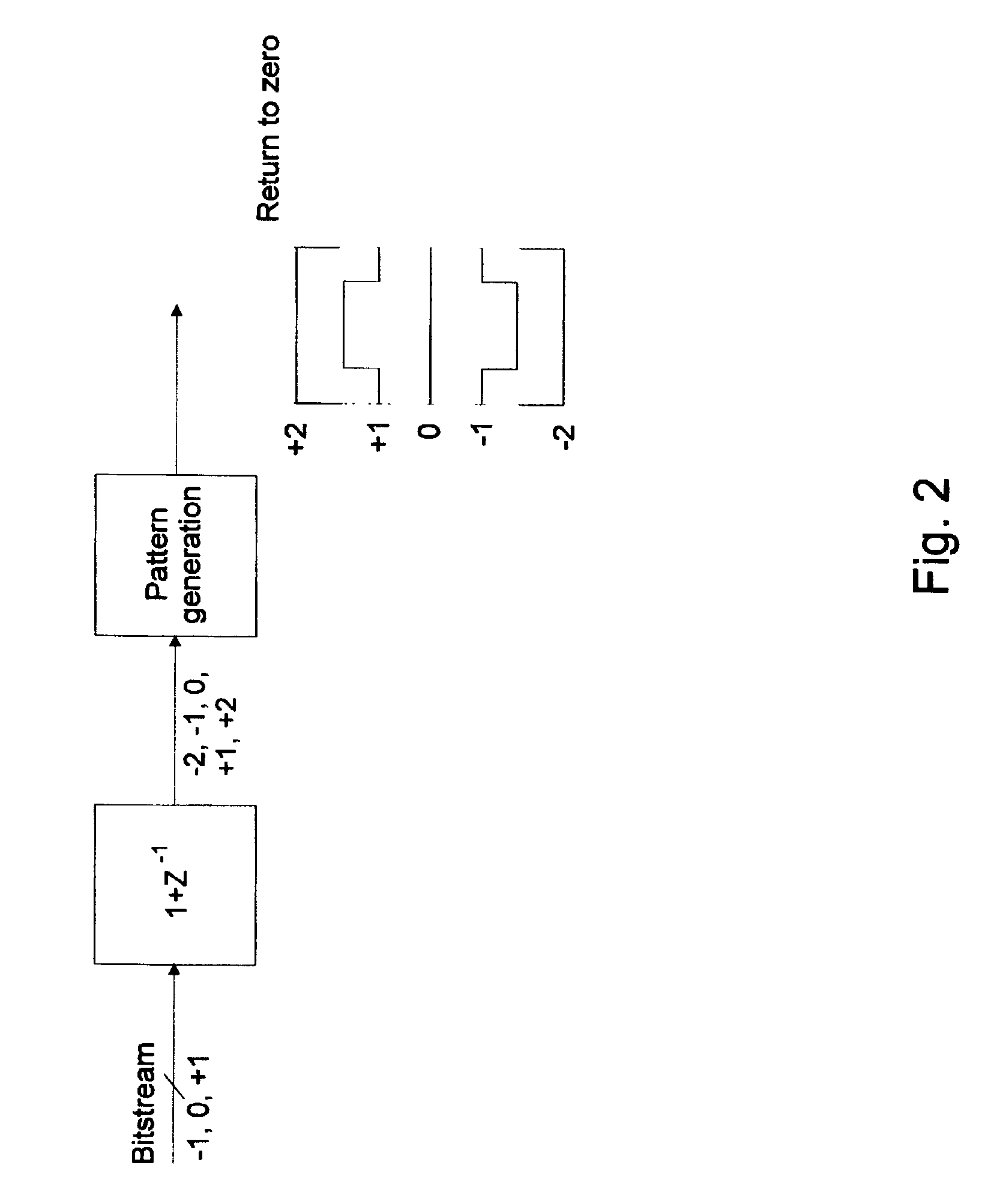
[0026]In FIG. 1, an example of a block diagram of a loudspeaker driver according to the present invention is depicted. Only the most commonly used signal processing blocks are shown. As the active signal processing circuit is mainly digital it is very easy to add additional functionalities. This could for example be a volume control, PLL filters etc. The input signal is a digital signal. Preferably, the parts are implemented on a single chip, such as an ASIC (Application Specific Integrated Circuit). Among these parts are a digital interface, an interpolator, a sigma-delta modulator, a regulator and an H-bridge. The correction block facilitates the control of the H-bridge in order to compensate for non-linearities. This block is essential and is described in further details in FIG. 2. In FIG. 1, the output from the chip is connected to the loudspeaker via a low-pass filter for removing high frequency noise caused by the loudspeaker driver. This filter is optional and can be avoided ...


PUM


Abstract

In a first aspect the present invention provides a compact high efficiency driver suitable for driving a loudspeaker, such as a miniature loudspeaker for mobile phones or hearing aids. The driver comprising an interface for receiving an input signal, a three-level modulator, and a three-level H-bridge. The interface may be adapted to receive a digital input signal. In a preferred embodiment of the driver the H-bridge is controlled by a correction circuit which is operated by a Return-To-Zero scheme. In a further preferred embodiment the driver comprises a supply voltage step-up circuit for increasing a voltage supplied to the H-bridge. In a second aspect the present invention provides a miniature loudspeaker assembly having a built-in driver. In a third aspect the present invention provides a mobile device with a built-in miniature loudspeaker assembly.

Description

FIELD OF THE INVENTION[0001]The present invention relates to a driver for an acoustical miniature transducer. In particular, the present invention relates to a loudspeaker driver providing high efficiency. In addition, the present invention relates to a miniature loudspeaker assembly having a built-in driver.BACKGROUND OF THE INVENTION[0002]Miniature loudspeakers are widely used in a variety of small portable devices, such as mobile phones, music players, personal digital assistants, hearing aids, earphones, portable ultrasonic equipment, and so forth, where small dimensions are paramount. Users of such devices appreciate their small dimensions, but would prefer not to compromise regarding sound quality. However, these devices are typically battery operated, which further limits the amount of electrical power available to drive the miniature loudspeaker. Also the fact that many of these applications are very sensitive to price dictates that production costs should be very low. Very ...

Claims


Application Information

Patent Timeline
IPC IPC(8): H04R3/00H03F3/38
CPCH04R3/00H04R1/005H04R25/505
Inventor FURST, CLAUS ERDMANNSTENBERG, LARS JORNPOULSEN, JENS KRISTIANTHOMSEN, HENRIK
Owner TDK CORPARATION
Learn More