Plastic heating duct connectors

a technology of plastic heating ducts and connectors, which is applied in the direction of hose connections, heating types, lighting and heating apparatus, etc., can solve the problems of metal ducts losing a considerable amount of heat to an uninsulated air space, razor sharp ends, etc., and achieves the improvement of duct performance, poor conductors, and the effect of overcoming metal duct deficiencies

Active Publication Date: 2008-03-04
DURA TITE SYST
View PDF24 Cites 18 Cited by
  • Summary
  • Abstract
  • Description
  • Claims
  • Application Information

AI Technical Summary

Benefits of technology

[0004]The present invention overcomes the deficiencies of metal ducts. Plastic duct is safer to handle, having no razor sharp edges. Further, plastic is a poor conductor of both heat and electricity, significantly reducing the btu's lost through the walls of the connectors. Further, tolerances on the plastic ducts can be held tighter and, plastics are not prone to denting, so junctions form tighter seals resulting in reduced air and heat loss at the junctions.

Problems solved by technology

Metal ducts pose a number of problems.
First, when the duct is cut to length, the end is razor sharp and poses a handling hazard.
Secondly, metal is a good conductor of heat (and electricity) and without insulation, the metal duct will lose a considerable amount of heat to an uninsulated air space.
Insulating the duct is an expensive alternative, although a prudent building owner will recoup the expense over time in energy saved, especially given the projected short-term increase in fuel costs.
Thirdly, metal fittings are difficult to seal properly.
Any denting of the metal further exacerbates the problem of sealing the connection.
The process of using the mastics is messy and both the taping and mastic application are time consuming.
Further, plastic is a poor conductor of both heat and electricity, significantly reducing the btu's lost through the walls of the connectors.

Method used


Image

  • Plastic heating duct connectors
  • Plastic heating duct connectors
  • Plastic heating duct connectors

Examples


first embodiment

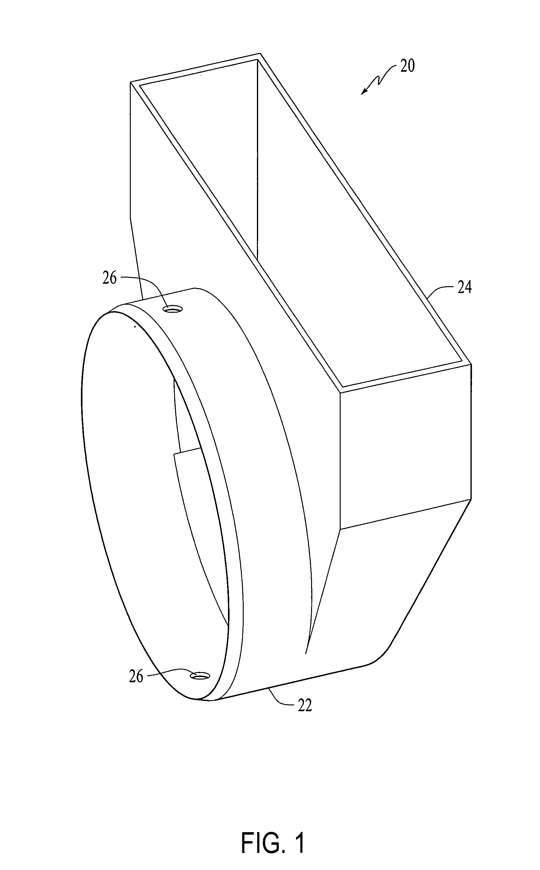
[0018]a plastic boot which forms a part of the present invention is shown in FIG. 1 generally at 20. Boot 20 is made as a one-piece injection molded plastic. The plastic used to make any of the embodiments shown herein is selected from the group consisting of acrylonitrile butadiene styrene (ABS), polyvinyl chloride (PVC), liquid crystal polymer (LCP) resin and polyphenylene sulfide (PPS), polypropylene (PP) and polyethylene (PE). Boot 20 has a cylindrical collar 22 and a rectangular body portion 24 which will engage a floor mounted exhaust grate or a rectangular extension which connects to such a grate. A plurality of holes 26 in collar 22 permit screws to attach a length of duct to boot 20. Boot 20 can be used with metal duct or flex duct.

second embodiment

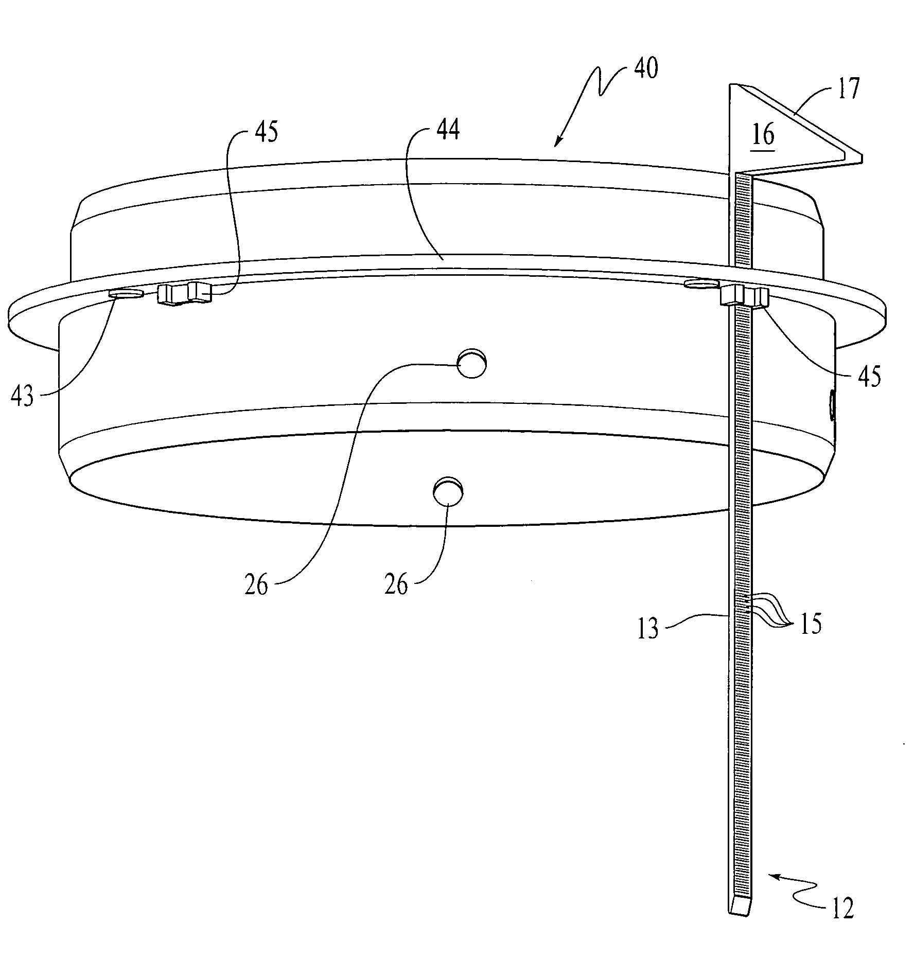
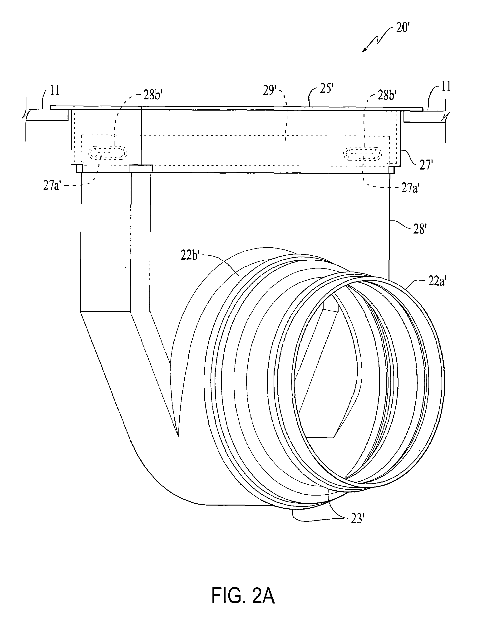
[0019]plastic boot is shown in FIGS. 2A and 2B generally at 20′. Plastic boot 20′ is formed with two collars 22a′ and 22b′ which can accommodate different diameter ducts (not shown). Plastic boot 20′, and in fact, each of the embodiments depicted herein, can be used with any type of duct including, but not limited to, metal duct and flex duct. In this embodiment, collars 22a′ and 22b′ are each formed with an annular ridge 23′ which is inserted into the duct which attaches thereto and functions as frictional securing means therefor. If used with flex duct, a hose clamp can be used outside the ridge 23′ to provide improved sealing. A rectangular fitting 25′ is mounted above a floor 11 with a sleeve 29′ which extends through the floor 11. Sides 27′ each have a rectangular protrusion 27a′ which snap into rectangular recesses 28b′ in rectangular upper portion 28′ of boot 20′ to secure the two members together.

[0020]FIG. 3 depicts a first embodiment of a boot adapter generally at 30. Adap...


PUM


Abstract

A connector for connecting a terminal end of a heating duct to a heating duct board, the connector including an annular cylindrical portion with an outer surface and a maximum outer diameter and a flange extending radially outwardly from the outer surface of the annular cylindrical portion. The flange has a dimension greater than the maximum diameter forming an abutment against which a lower edge of the heating duct board abuts. The flange also has at least one sleeve for receiving a zip tie. The connector includes retention means for securing the connector to the heating duct board with the heating duct board encircling the annular cylindrical portion and being in abutting engagement with the flange. The retention includes at least one zip tie mounted through the at least one sleeve of the flange and engageable in a mouth of the heating duct board to which the connector is secured.

Description

BACKGROUND AND SUMMARY OF THE INVENTION[0001]The present invention is directed to the field of heating ducts. More particularly, the present invention is directed to duct boots, connectors and the like, made of plastic. This invention is related to jointly owned U.S. Pat. No. 6,196,597 entitled “Heating Duct”, which is hereby incorporated by reference.[0002]The majority of duct being installed in residential and commercial units is fabricated of sheet metal, although, recently, flex duct has become more widely used. Metal ducts pose a number of problems. First, when the duct is cut to length, the end is razor sharp and poses a handling hazard. Secondly, metal is a good conductor of heat (and electricity) and without insulation, the metal duct will lose a considerable amount of heat to an uninsulated air space. Insulating the duct is an expensive alternative, although a prudent building owner will recoup the expense over time in energy saved, especially given the projected short-term...

Claims


Application Information

Patent Timeline
Patent Type & Authority Patents(United States)
IPC IPC(8): F16L21/00
CPCF16L41/02F24F13/0209F16L41/025Y10T24/1498
Inventor KARNES, JAMES A.
Owner DURA TITE SYST
Why Eureka
Try Eureka