Multilayer composite and method of making same

a composite material and multi-layer technology, applied in the field of composite materials, can solve the problems of composites of fluoropolymers and nonfluoropolymers to exhibit low interfacial peel strength, a tendency to delaminate, and low peel strength of composites of fluoropolymers and nonfluoropolymers, and the film of less thickness is usually too weak to be self-supporting or to withstand normal manipulation experienced

Inactive Publication Date: 2008-03-04
SAINT GOBAIN PERFORMANCE PLASTICS CORP
View PDF35 Cites 10 Cited by
  • Summary
  • Abstract
  • Description
  • Claims
  • Application Information

AI Technical Summary

Benefits of technology

[0015](D) optionally applying additional dispersion onto the outboard face and heating the web and dispersion to a temperature above the fusing temperature for a duration effective to remove additional liquid medium and to build up thickness of the film of the protective layer,

Problems solved by technology

Such superior surface properties are generally lacking in low-cost, curable liquid rubber compositions but are typically exhibited by more-costly halogen-containing polymers, especially fluoropolymers.
Unfortunately and ironically, the highly prized surface properties which make fluoropolymers poorly adherent to dissimilar materials also causes the desirable laminar composites of fluoropolymers and nonfluoropolymers to exhibit low interfacial peel strength and a tendency to delaminate.
Film of less thickness is usually too weak to be self-supporting or to withstand normal manipulation experienced during the fabrication of the composite.
Thin film can be produced by carefully skiving sections from a fluoropolymer billet, however this is a very difficult procedure to carry out successfully.
Naturally, these thin films are extremely delicate and must be handled with extreme care to maintain their structural integrity.

Method used


Image

  • Multilayer composite and method of making same
  • Multilayer composite and method of making same
  • Multilayer composite and method of making same

Examples


example 1

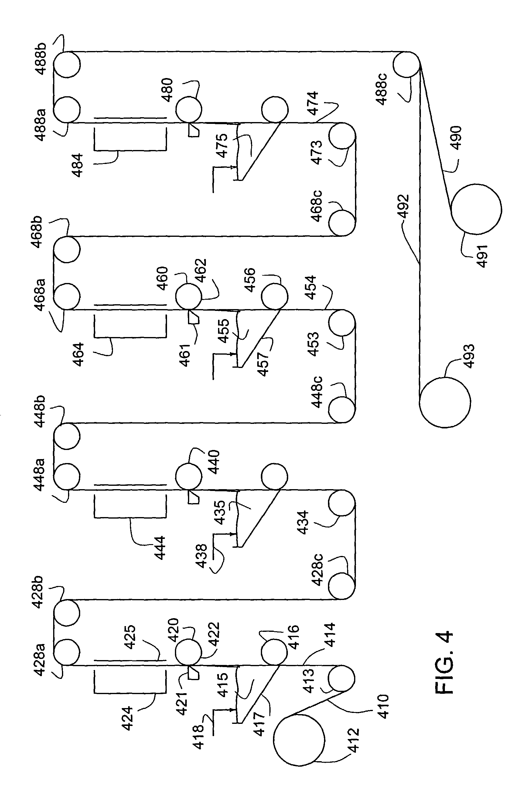
[0080]A multilayer composite was produced using a single stage coating tower assembly similar to that illustrated in FIG. 6. A carrier web of Kapton® polyimide film from DuPont of 0.13 μm (0.005 inch) thick and 0.55 m (22 inches) wide was continuously drawn from a supply roll and passed at 4.9 m / min. (16 ft. / min.) under a 5.1 cm (2 inch) diameter idler roll. The idler roll was submerged in a bath containing Fluon® AD1LN PTFE aqueous dispersion to which 0.5% Zonyl® FSO fluorosurfactant from DuPont had been added to modify the surface tension. The modified aqueous dispersion was diluted with deionized water to achieve a specific gravity of 1.38.

[0081]The carrier web was directed upward and thus emerged from the bath coated on both sides with the dispersion. Above the surface of the bath the dispersion-coated web passed between a pair of stationary Mayer-type metering rods of 12.7 mm (0.5 inch) diameter which were wound with 0.64 mm (0.025 inch) diameter wire. The rods were oriented pa...

examples 2-5

[0087]Composites were manufactured similarly to the procedure of Example 1 as described more fully below. Selected conditions for making each sample and product physical properties are shown in Table I.

[0088]In Example 2, the procedure of Ex. 1 was followed except that the reinforcement fabric was Ahlstrom product 3257 (Ahlstrom Filtration Specialties, Mt. Holly Springs, Pa.) and the gap between the rods for metering the LSR pick up was 0.2 mm (0.008 inch) which caused a pick up of 0.038 mm of LSR. Due to the relative thicknesses of the LSR and the reinforcement, the latter was fully embedded within the second polymeric layer, (i.e., both inboard and outboard faces of the fabric were impregnated with LSR). After removal from the carrier web, the exposed face of the protective layer was smooth and glossy, and the exposed face of the second polymeric layer was slightly textured due to the presence of the reinforcement just beneath the surface.

[0089]In Example 3, the procedure of Ex. 2...

examples 6-10

[0093]A number of multilayer composites were manufactured according to this invention in a fashion similar to the procedure of the preceding examples in which different LSR compositions were utilized. Selected process conditions and product physical properties are shown in Table II. Table III describes the LSR compositions used in the examples.

[0094]In Example 6 the procedure of example 2 was repeated except that the reinforcement material was a plain weave fabric of style 89 glass fiber and the liquid silicone rubber (LSR) composition was (II) (see Table III). The reinforcement was fully embedded within the translucent LSR second polymeric layer.

[0095]Example 7 was produced identically to Ex. 6 except that the LSR composition (IV) was used. The resulting LSR second polymeric layer was fire resistant due to a fire retardant agent included in the LSR composition by the supplier.

[0096]Example 8 was the same as Ex. 7 except that the reinforcement layer was a polyester plain weave fabri...


PUM

PropertyMeasurementUnit
thicknessaaaaaaaaaa
glossaaaaaaaaaa
thicknessaaaaaaaaaa

Abstract

A multilayer composite has a generally adhesion resistant, protective layer and an adjacent second polymeric film. The composition of the protective layer includes a fluoropolymer and the second polymeric film is a polymer free of fluoropolymer. The size of the protective layer facing the second polymeric layer is rendered bondable to the non-fluoropolymer of the second polymeric layer prior to assembling the layers in the composite. The composite is well adapted to being produced in a vertical coating tower. The tower utilizes a carrier web onto which the fluoropolymer layer and second polymeric layer are deposited from respective casting films. Mirror image composites can be formed simultaneously on opposite sides of the carrier web.

Description

FIELD OF THE INVENTION[0001]This invention relates to a composite material having a very thin exposed first polymeric layer of a fluoropolymer composition bonded to a second polymeric layer of a composition substantially free of fluoropolymer. More specifically, the invention relates to a multilayer composite comprising a fluoropolymer protective layer thinner than about 51 μm (2 mils) and a second polymeric layer formed and bonded to the protective layer by curing a fluoropolymer-free, liquid silicone elastomer. The composite can have an optional fabric or film reinforcement layer adjacent or embedded in the second polymeric layer.BACKGROUND OF THE INVENTION[0002]Many commercially available curable liquid rubber polymer compositions exhibit a wide range of useful mechanical, physical and electrical bulk properties. Additionally these compositions can be provided at relatively low cost. There is a continuing need for materials with such useful properties in diverse applications whic...

Claims


Application Information

Patent Timeline
Patent Type & Authority Patents(United States)
IPC IPC(8): B32B37/00B29C41/32B32B27/12B32B37/26B32B38/00C08J5/02
CPCB29C41/32B32B27/12B32B37/26C08J5/02B29K2027/12B32B37/0038B32B2037/243B32B2037/268B32B2038/0076B32B2305/08B32B2305/18B32B2319/00B32B2327/12Y10T428/3154B32B27/08B32B27/322B32B2307/406
Inventor SPOHN, PETER DKEESE, FRANK MSINOFSKY, MARK W
Owner SAINT GOBAIN PERFORMANCE PLASTICS CORP
Why Eureka
Try Eureka