Multi frequency magnetic dipole antenna structures and method of reusing the volume of an antenna

a magnetic dipole antenna and multi-frequency technology, applied in the direction of loop antennas, radiating element structural forms, resonance antennas, etc., can solve the problems of polarization loss, partial loss of signal, and impaired reception and/or transmission, and achieve the effect of increasing the ratio of relative bandwidth to volum

Inactive Publication Date: 2008-03-04
KYOCERA AVX COMPONENTS (SAN DIEGO) INC
View PDF27 Cites 32 Cited by
  • Summary
  • Abstract
  • Description
  • Claims
  • Application Information

AI Technical Summary

Benefits of technology

[0012]In a preferred embodiment, the basic antenna element comprises a substantially planar structure with a planar conductor and a pair of parallel elongated conductors, each having a first end electrically connected to the planar conductor. Additional elements may be coupled to the basic element in an array. In this way, individual antenna structures share common elements and volumes, thereby increasing the ratio of relative bandwidth to volume.

Problems solved by technology

An antenna must be tuned to the same frequency band that the radio system operates in, otherwise reception and / or transmission will be impaired.
If it is not oriented properly, a portion of the signal is lost, known as polarization loss.

Method used


Image

  • Multi frequency magnetic dipole antenna structures and method of reusing the volume of an antenna
  • Multi frequency magnetic dipole antenna structures and method of reusing the volume of an antenna
  • Multi frequency magnetic dipole antenna structures and method of reusing the volume of an antenna

Examples


Embodiment Construction

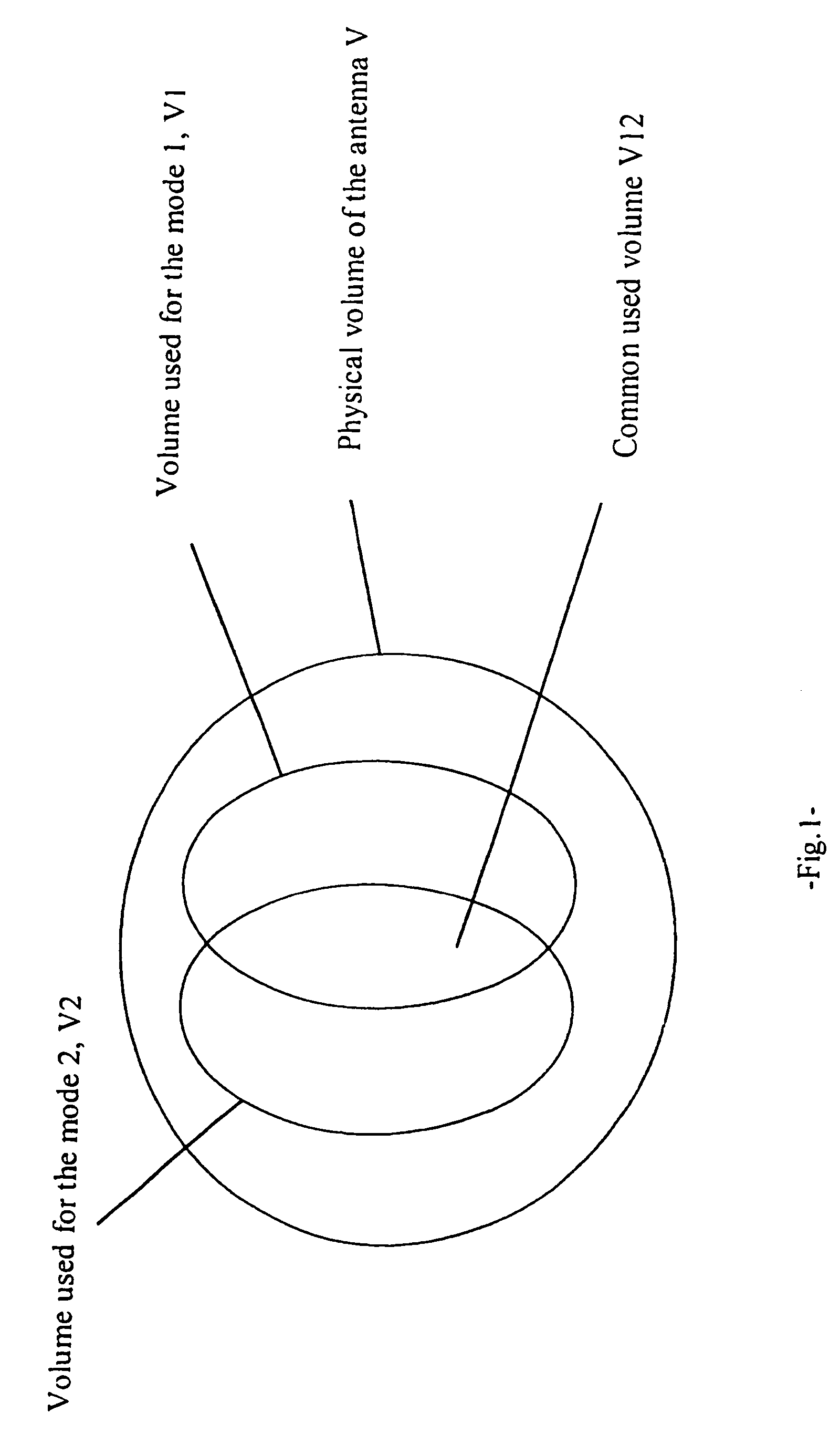
[0039]The volume to bandwidth ratio is one of the most important constraints in modern antenna design. The physical volume of an antenna can place severe constraints on the design of small electronic devices. One approach to increasing this ratio is to re-use the volume for different modes. Some designs already use this approach, even though the designs do not optimize the volume to bandwidth ratio. In these designs, two modes are generated using the same physical structure, although the modes do not use exactly the same volume. The current repartition of the two modes is different, but both modes nevertheless use a common portion of the total available volume of the antenna. This concept of utilizing the physical volume of the antenna for a plurality of antenna modes is illustrated generally by the Venn Diagram of FIG. 1. The physical volume of the antenna (“V”) has two radiating modes. The physical volume associated with the first mode is designated ‘V1’, whereas that associated w...


PUM


Abstract

Various resonant modes of a multiresonant antenna structure share at least portions of the structure volume. The basic antenna element has a substantially planar structure with a planar conductor and a pair of parallel elongated conductors, each having a first end electrically connected to the planar conductor. Additional elements may be coupled to the basic element in an array. In this way, individual antenna structures share common elements and volumes, thereby increasing the ratio of relative bandwidth to volume.

Description

CROSS REFERENCE TO RELATED APPLICATIONS[0001]This application is a continuation-in-part of application Ser. No. 10 / 253,016 filed Sep. 23, 2002 now U.S. Pat. No. 7,012,568, which is a continuation of application Ser. No. 09 / 892,928 filed Jun. 26, 2001, now U.S. Pat. No. 6,456,243, the disclosure of which is incorporated herein by reference.[0002]This application relates to U.S. Pat. No. 6,323,810, titled “Multimode Grounded Finger Patch Antenna” by Gregory Poilasne et al., owned by the assignee of this application and incorporated herein by reference.[0003]This application also relates to application Ser. No. 09 / 781,779, is now abandoned titled “Spiral Sheet Antenna Structure and Method” by Eli Yablonovitch et al., owned by the assignee of this application and incorporated herein by reference.[0004]This application also relates to application Ser. No. 10 / 076,922 filed Feb. 14, 2002, now U.S. Pat. No. 6,906, 667 titled “Multifrequency Magnetic Dipole Antenna Structures for Very Low Pr...

Claims


Application Information

Patent Timeline
Patent Type & Authority Patents(United States)
IPC IPC(8): H01Q1/24H01Q1/38H01Q5/00H01Q5/342H01Q5/357H01Q5/378H01Q7/00H01Q9/04H01Q9/28
CPCH01Q1/38H01Q7/00H01Q9/0414H01Q5/378H01Q9/28H01Q5/342H01Q5/357H01Q9/0421H01Q1/24H01Q5/00
Inventor DESCLOS, LAURENTPOILASNE, GREGORYSHAMBLIN, JEFFROWSON, SEBASTIAN
Owner KYOCERA AVX COMPONENTS (SAN DIEGO) INC
Why Eureka
Try Eureka