PLL clock generator, optical disc drive and method for controlling PLL clock generator

a clock generator and optical disc drive technology, applied in the field of phaselocked loops, can solve the problems of reducing the overall circuit scale unintentionally, affecting the stability of the pll clock generator, so as to achieve phase locking quickly enough, reduce jitter, and simplify the configuration

Inactive Publication Date: 2008-03-04
PANASONIC CORP
View PDF7 Cites 15 Cited by
  • Summary
  • Abstract
  • Description
  • Claims
  • Application Information

AI Technical Summary

Benefits of technology

[0012]In order to overcome the problems described above, preferred embodiments of the present invention provide a PLL clock generator, which has a simple configuration but which can accomplish phase locking quickly enough with the jitter minimized, and also provide an optical disc drive including such a PLL clock generator.
[0025]According to various preferred embodiments of the present invention described above, the phase of the output signal of the frequency divider is preferably controlled in accordance with a phase difference signal, thereby changing the response characteristic of a feedback loop, made up of the frequency divider, phase comparator, low pass filter and voltage-controlled oscillator, without switching the characteristics of the charge pump or low pass filter. Thus, it is possible to prevent the PLL clock generator from increasing its circuit scale.
[0026]In addition, the phase shifter can control the phase of the output signal of the frequency divider even outside of the phase locking range without depending on the characteristic of the charge pump or low pass filter. Accordingly, in the feedback loop consisting of the frequency divider, phase comparator, low pass filter and voltage-controlled oscillator, if the low pass filter is designed so as to minimize the jitter of the clock signal, then the capture range can be expanded and the jitter can be minimized at the same time.
[0027]Furthermore, phase locking can be accomplished quickly enough by performing a feedback control with the loop consisting of the frequency divider, phase comparator, low pass filter and voltage-controlled oscillator and by getting the phase of the output signal of the frequency divider shifted by the phase shifter.

Problems solved by technology

However, if the cutoff frequency of the low pass filter 503 is decreased, then it will take a longer time for the PLL clock generator to accomplish phase locking or the capture range (i.e., a frequency range in which phase locking can be accomplished) may narrow.
That is to say, some tradeoff is inevitable between the jitter minimization of the wobble clock signal and the time it takes to accomplish phase locking in the PLL clock generator or the phase-locking frequency range.
However, to switch the loop gain of the PLL in this manner, a circuit for changing the amounts of current to be pumped by the charge pump is needed, thus increasing the overall circuit scale unintentionally.
Furthermore, if the response of the PLL is accelerated by increasing the loop gain thereof, then the PLL will have a decreased phase margin and easily lose its stability (e.g., phase locking state once accomplished collapses easily).

Method used


Image

  • PLL clock generator, optical disc drive and method for controlling PLL clock generator
  • PLL clock generator, optical disc drive and method for controlling PLL clock generator
  • PLL clock generator, optical disc drive and method for controlling PLL clock generator

Examples


embodiment 1

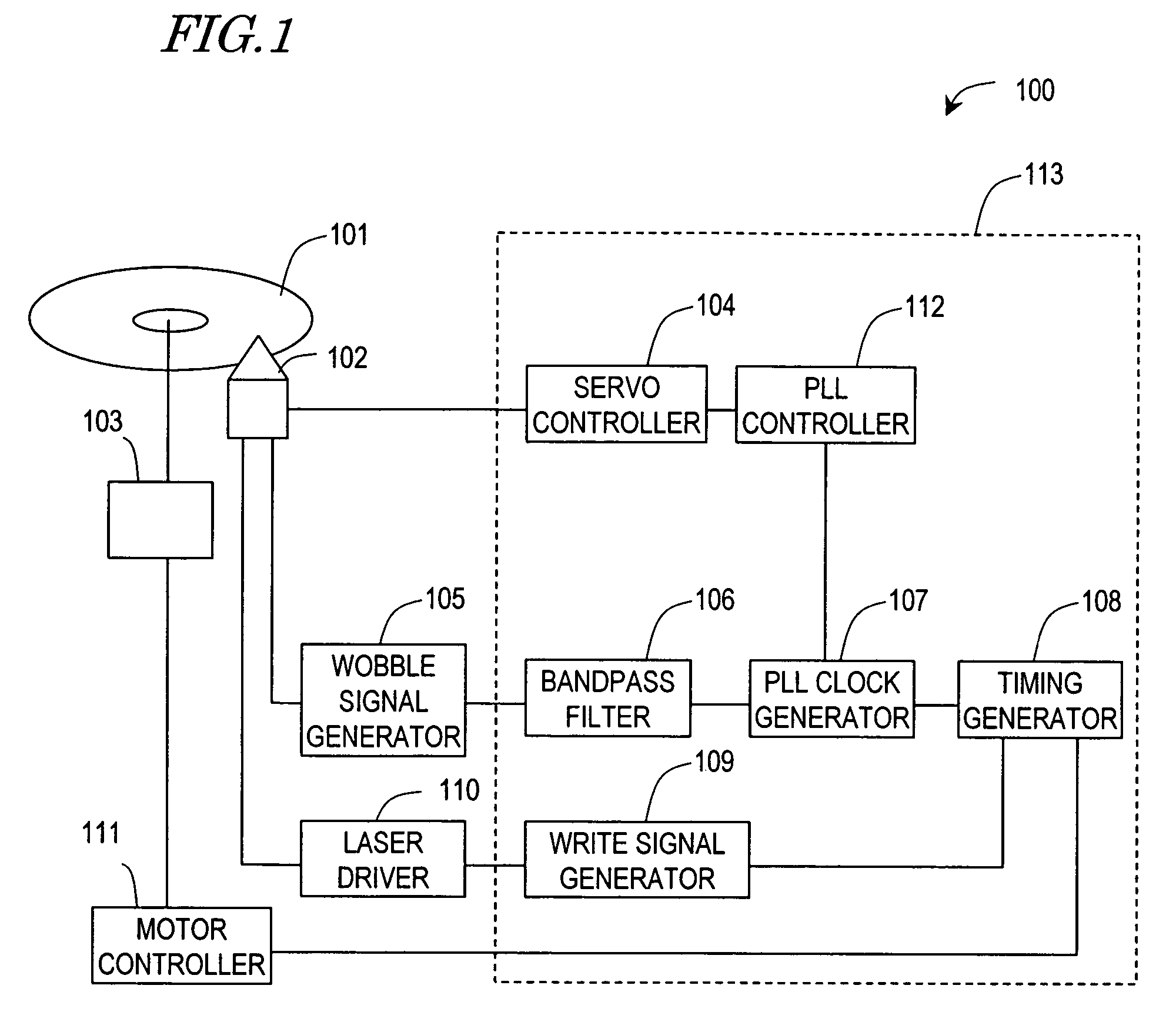
[0037]FIG. 1 is a block diagram showing a configuration for an optical disc drive according to a first specific preferred embodiment of the present invention. As shown in FIG. 1, the optical disc drive preferably includes an optical head 102, a spindle motor 103, a servo controller 104, a wobble signal generator 105 and a motor controller 111.

[0038]The spindle motor 103 preferably includes a turntable to mount an optical disc 101 thereon and preferably rotates and drives the optical disc 101 under the control of the motor controller 111.

[0039]The servo controller 104 preferably performs a focus control and a tracking control on the optical head 102 such that the light emitted from the optical head 102 is focused right on the optical disc 101 and follows a target track on the disc 101 just as intended.

[0040]The optical head 102 preferably includes a photodetector (not shown), which has a number of light detecting areas that are split perpendicularly to the tracks (i.e., in the radial...

embodiment 2

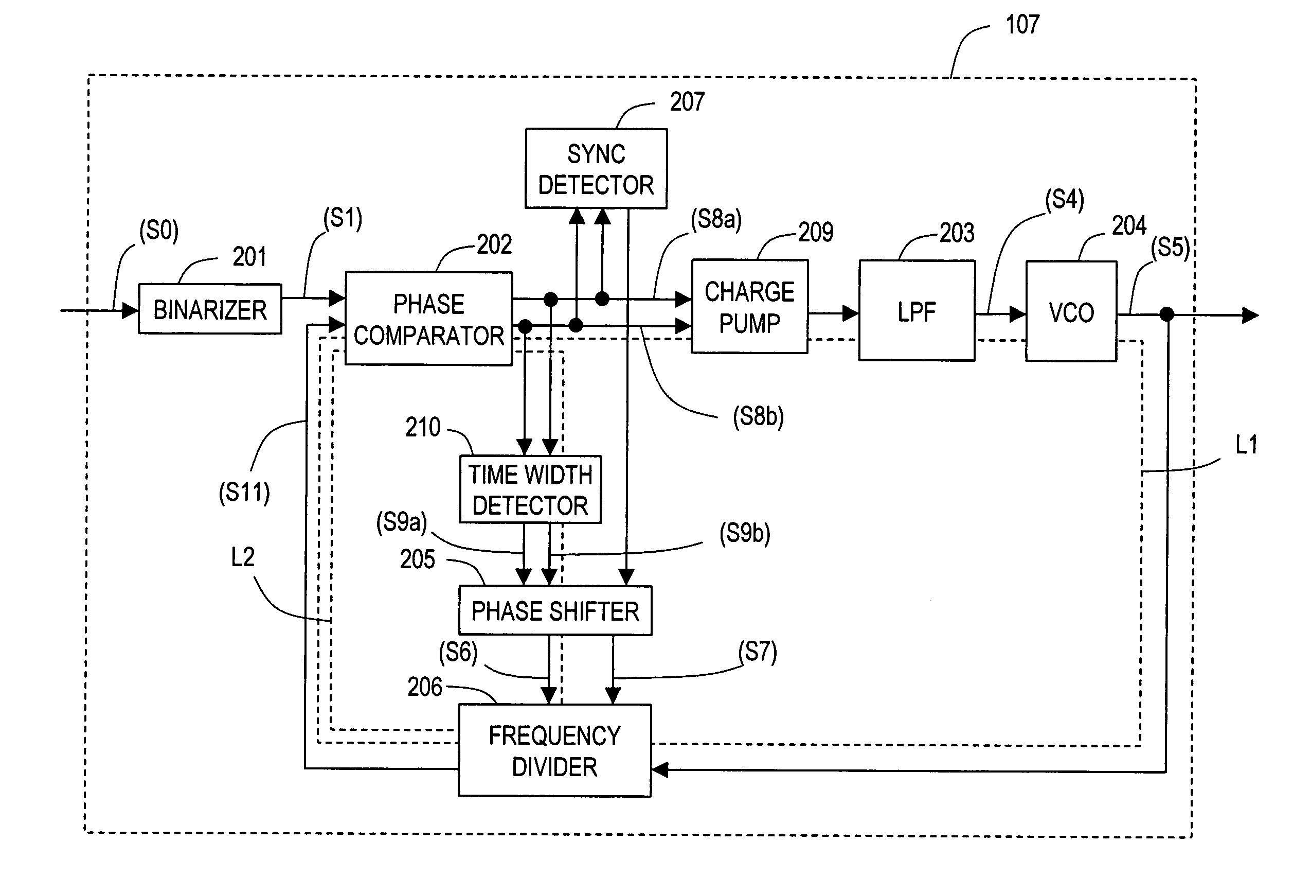
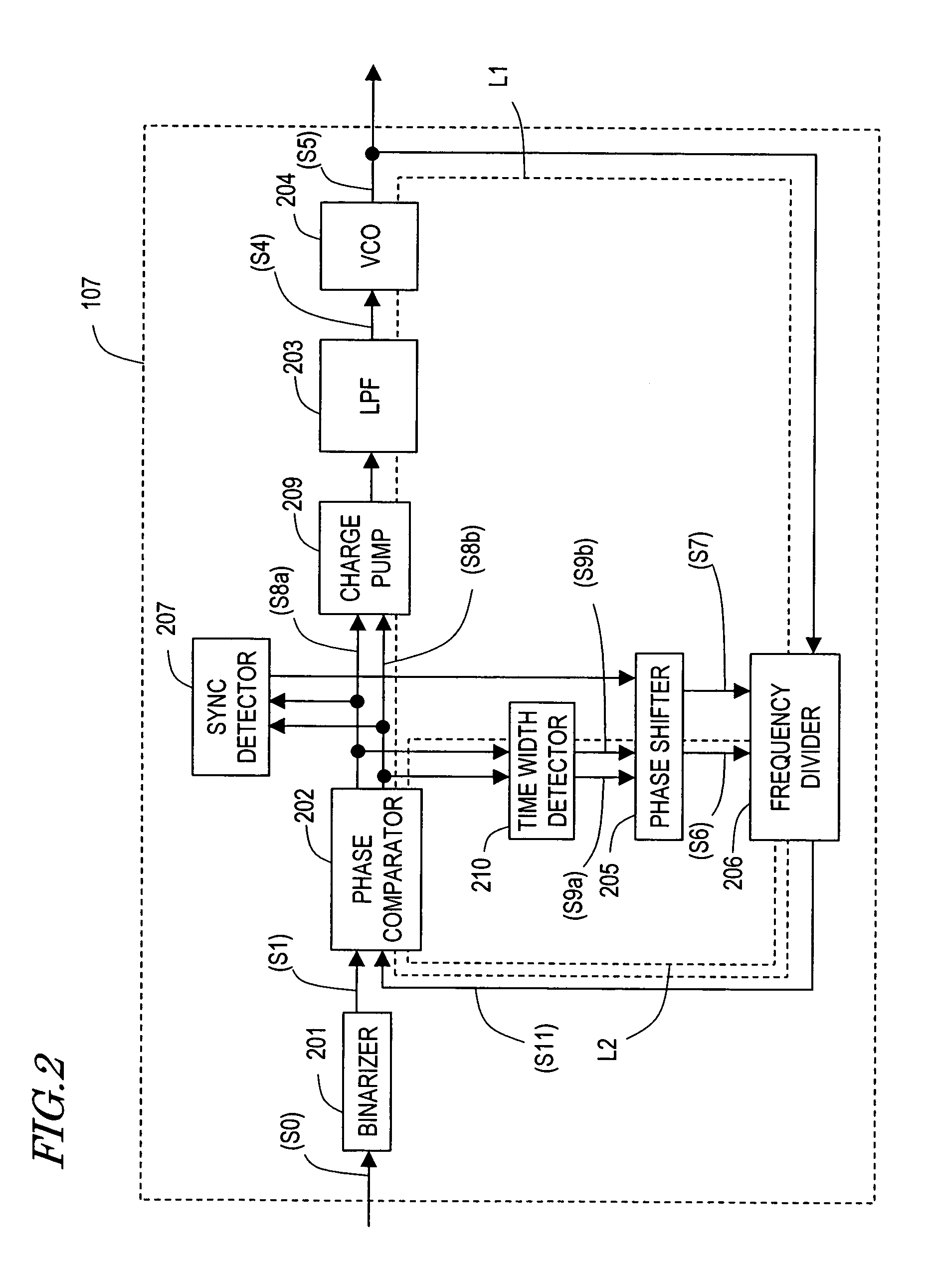
[0064]FIG. 5 is a block diagram showing a configuration for a PLL clock generator according to a second specific preferred embodiment of the present invention. Just like the PLL clock generator 107 of the first preferred embodiment described above, the PLL clock generator 107′ of this second preferred embodiment can also be used effectively as the PLL clock generator 107 of the optical disc drive 100. FIG. 6 shows the waveforms of internal signals for respective components of the PLL clock generator 107′ shown in FIG. 5. As in the first preferred embodiment described above, the PLL clock generator 107′ preferably also performs feedback controls using the loops L1 and L2 and preferably generates a wobble clock signal from a wobble signal. However, the second preferred embodiment is different from the first preferred embodiment in that part of signal processing by the loop L1 and all of signal processing by the loop L2 are carried out by using digital signals.

[0065]As shown in FIG. 5,...


PUM

PropertyMeasurementUnit
frequencyaaaaaaaaaa
frequencyaaaaaaaaaa
frequencyaaaaaaaaaa

Abstract

A PLL clock generator generates an output signal with a frequency N times (where N≧1) as high as that of an input signal. The clock generator includes: a frequency divider for dividing the frequency of a clock signal by N so as to output a frequency-divided clock signal; a phase comparator for detecting a phase difference between the input signal and the output signal of the frequency divider so as to output a phase difference signal including information representing the phase difference; a LPF for smoothing the phase difference signal; a VCO for generating the clock signal, of which the frequency is determined by the output of the LPF, and outputting the clock signal to the frequency divider; and a phase shifter for shifting the phase of the output signal of the frequency divider in accordance with the phase difference signal.

Description

BACKGROUND OF THE INVENTION[0001]1. Field of the Invention[0002]The present invention relates to a phase-locked loop (PLL) and more particularly relates to a PLL clock generator for generating clock pulses by reading a wobbling pattern on a given optical disc and to an optical disc drive including such a PLL clock generator.[0003]2. Description of the Related Art[0004]A recordable or rewritable optical disc such as a DVD-RAM, a DVD-R or a DVD-RW (which will be referred to herein as a “recordable optical disc” collectively) has spiral data recording tracks that wobble. A light beam that has been emitted toward, and reflected from, one of those recordable optical discs includes information representing modulation caused by the wobbling pattern on the optical disc (which will be referred to herein as “wobbling information”). A conventional optical disc drive generates a PLL multiplier clock signal in accordance with this wobbling information and uses that clock signal to perform a writ...

Claims


Application Information

Patent Timeline
Patent Type & Authority Patents(United States)
IPC IPC(8): G11B5/09H03L7/06H03L7/085H03L7/089
CPCH03L7/085H03L7/0891
Inventor MINAMINO, JUNICHINAKATA, KOHEI
Owner PANASONIC CORP
Why Eureka
Try Eureka