Evaporation apparatus

a technology of evaporation apparatus and evaporation chamber, which is applied in the direction of lighting and heating apparatus, separation processes, furnaces, etc., can solve problems such as inability to adap

Inactive Publication Date: 2008-03-11
GOULBURN WOOL SCOUR PTY LYD
View PDF7 Cites 16 Cited by
  • Summary
  • Abstract
  • Description
  • Claims
  • Application Information

AI Technical Summary

Benefits of technology

[0009]In use the evaporation chamber itself advantageously acts to contain the liquid to be evaporated, and to exclude rainwater and the activity of birds and animals. As a further example, an enclosed pool of liquid provides a large liquid / gas interfacial area for evaporation. Prior art apparatus is not adapted for containing a volume of liquid in a pool, and is merely arranged for evaporative drying of bulky solid goods. The evaporation apparatus of the invention represents an improvement over prior art apparatus because, being inflatable, the chamber does not require a complex inner or exterior support structure, allowing the apparatus to be readily collapsed and moved to a new location. The collapsible chamber of the invention thus represents a simple and cost effective solution for many evaporative drying processes because, being inflatable, it is relatively easy to set up and to operate, it can contain a large volume of liquid to be evaporated, and can be made internally accessible for periodic cleaning purposes.
[0013]Preferably the fluid flow control means is arranged to substantially prevent the ingress of a diluent liquid other than the liquid to be evaporated into the chamber. For example, the gas introduction and outlet holes in the chamber can be arranged to be very small in size or to be shielded or covered in some way, to prevent the ingress of, for example, rainwater.

Problems solved by technology

Prior art apparatus is not adapted for containing a volume of liquid in a pool, and is merely arranged for evaporative drying of bulky solid goods.

Method used


Image

  • Evaporation apparatus
  • Evaporation apparatus
  • Evaporation apparatus

Examples


Embodiment Construction

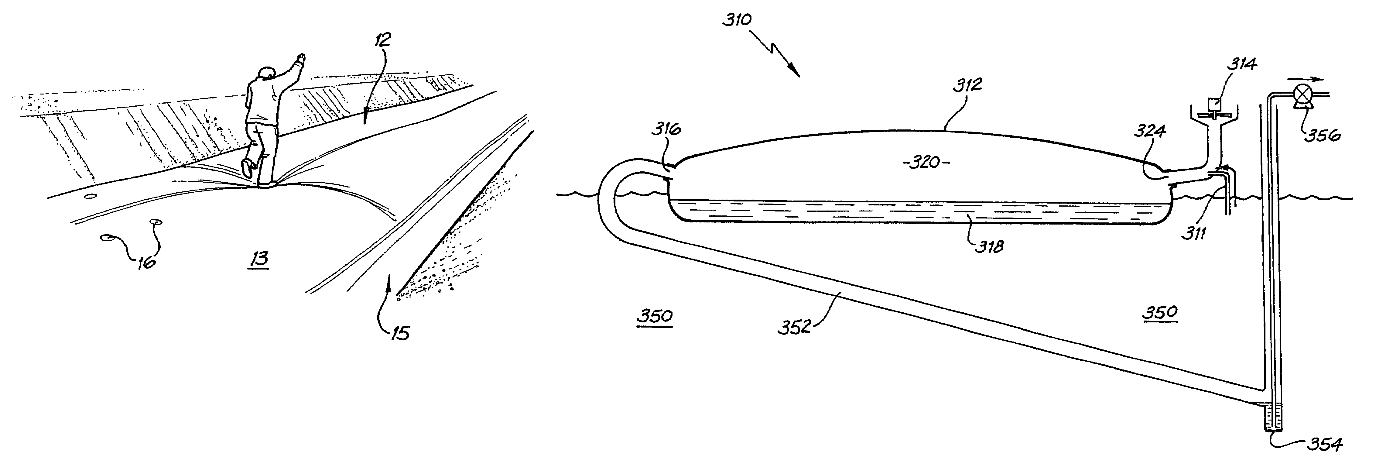
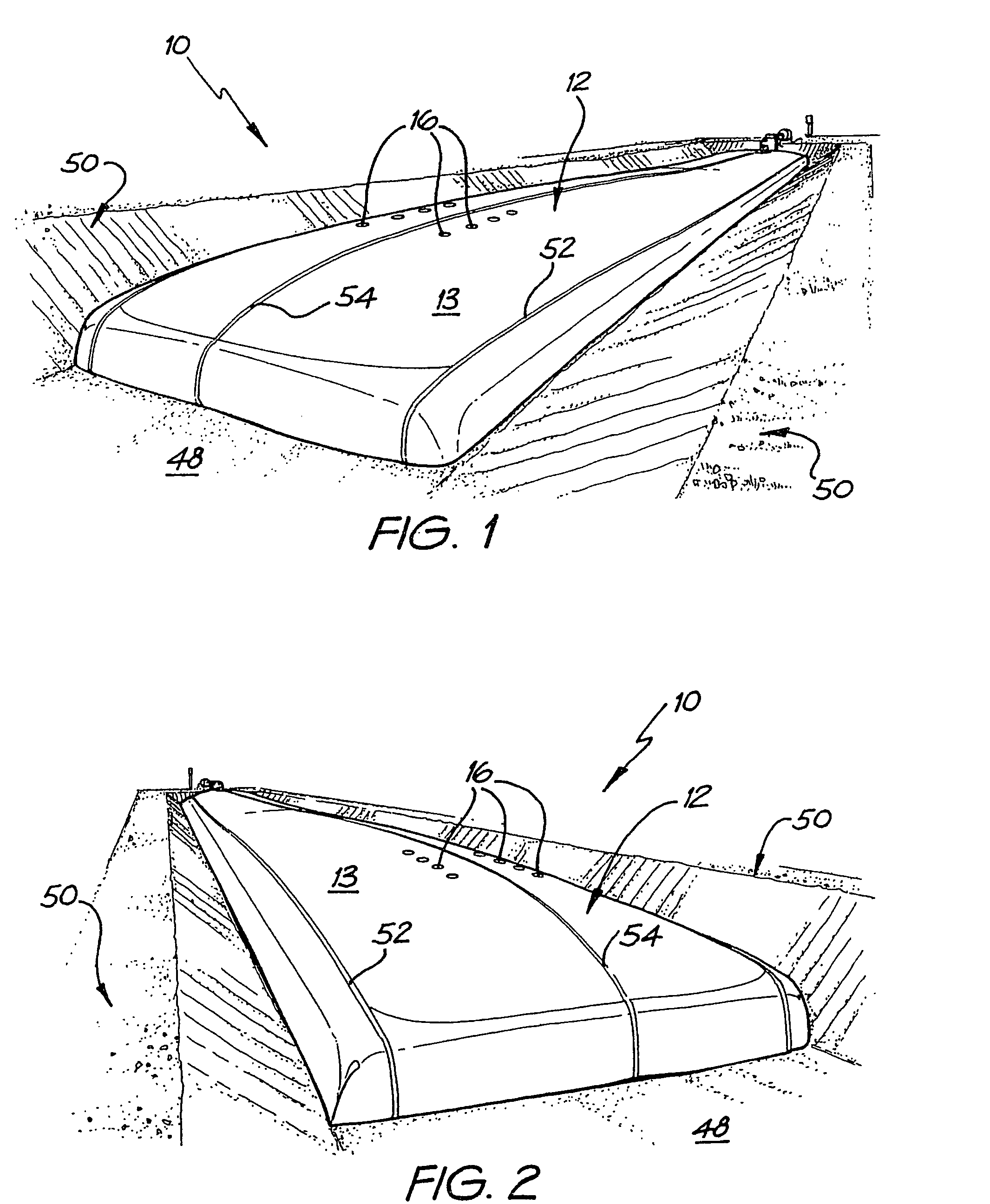
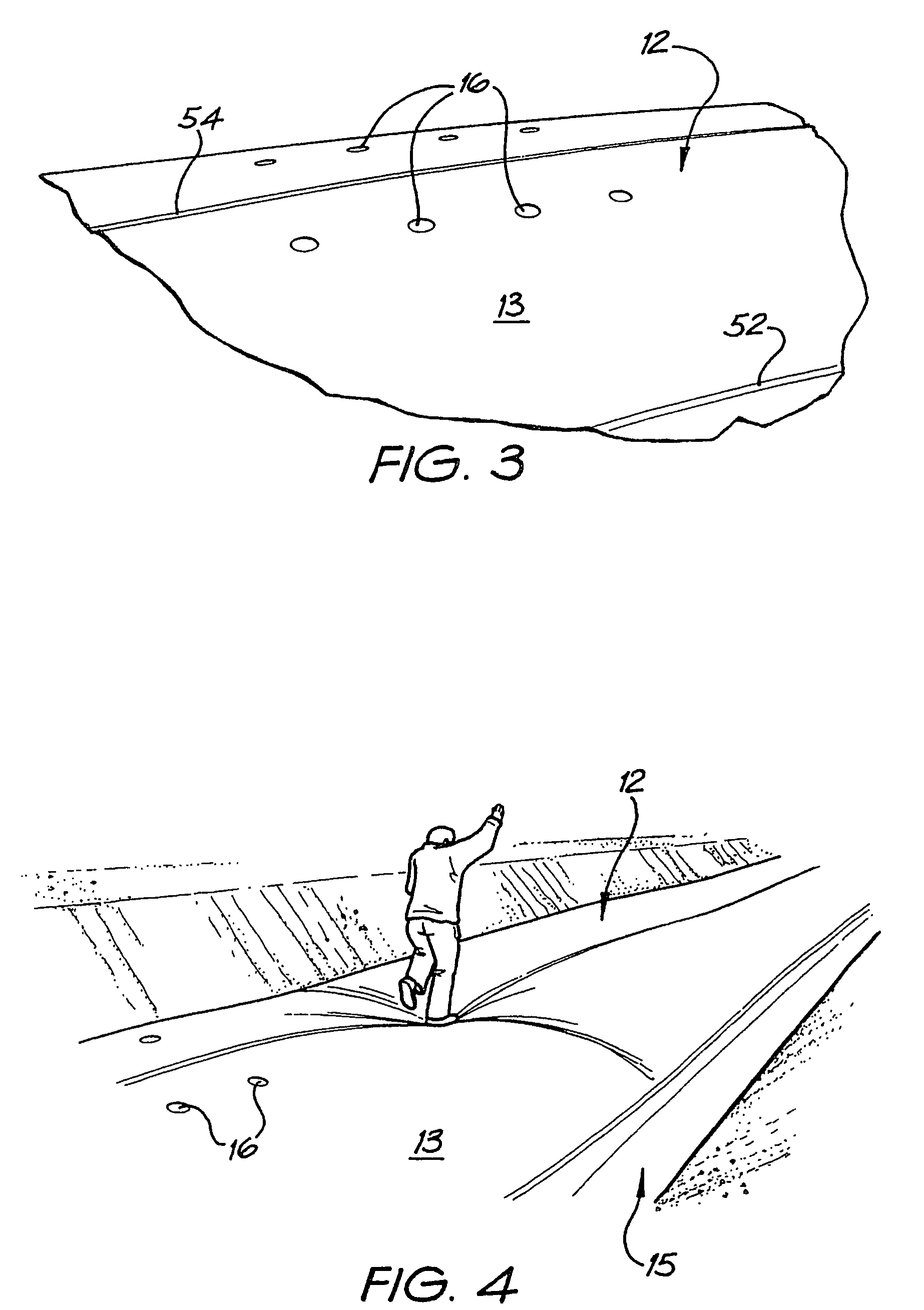
[0040]Referring to a preferred embodiment shown in FIGS. 1 to 5, an evaporation apparatus 10 is shown which comprises an evaporation chamber in the form of an inflatable elongate tube 12 that is fitted with fluid flow control means in the form of an inlet gas fan 14 and a number of gas outlet holes 16. The capacity of the inlet gas fan 14 and the size of the outlet holes 16 are matched so that the degree of inflation of the tube 12 can be maintained. The tube 12 is generally made of a thick-walled plastic material although other flexible materials suitable for containing gases and liquids are acceptable. A number of particularly preferred forms of plastic material are outlined in the following description.

[0041]In use the inflatable tube 12 is partially filled with a volume of liquid 18 to be evaporated, as shown schematically in FIG. 5. The liquid 18 may be accompanied by or include solid matter 19, for example as a slurry or pulp, or may even contain dissolved solids or salts. In ...


PUM

PropertyMeasurementUnit
flow rateaaaaaaaaaa
widthaaaaaaaaaa
widthaaaaaaaaaa

Abstract

An evaporation apparatus 10 is shown in the form of an inflatable elongate plastic tube 12 that is fitted with fluid control means in the form of an inlet gas fan 14 and a gas outlet hole 16. The capacity of the inlet gas fan 14 and the size of the outlet hole 16 are matched so that the degree of inflation of the tube 12 can be maintained. In use the inflated tube 12 is partially filled with a volume of liquid 18 in a pool at a base thereof to be heated and evaporated by solar radiation and carried out of the tube 12 by a flow of gas therethrough. The pool of liquid 18 may include solid matter 19, or even contain substances such as dissolved solids or salts. Over time a significant quantity of this material can become deposited in the tube 12, and can be reclaimed.

Description

[0001]This application is a U.S. National Phase of International Patent Application Ser. No. PCT / AU2003 / 001121, filed Sep. 1, 2003 which claims priority to Australian Patent Application No. 2002951103 filed Aug. 30, 2002.FIELD OF THE INVENTION[0002]The present invention relates to an evaporation apparatus. The apparatus can be applied to the evaporation of a waste water which contains suspended organic solid matter and will primarily be described with reference to this context. The invention has broad use in evaporative drying applications for all manner of other liquids which include particulate, dissolved or suspended substances.BACKGROUND ART[0003]Evaporative drying apparatus is known in the art, and can include basic drying basins or pans which are open to the atmosphere. In such equipment, reliance is placed on the sun or wind to evaporate a liquid-containing mixture placed in the drying basin or pan. On cloudy or cold days the evaporative process can be slowed or halted. In so...

Claims


Application Information

Patent Timeline
Patent Type & Authority Patents(United States)
IPC IPC(8): F26B19/00B01D1/30F26B3/28F26B9/00
CPCB01D1/30F26B3/286F26B9/006Y02B40/74F26B25/066F26B25/16Y02B40/18
Inventor KNEEBONE, HOWARD
Owner GOULBURN WOOL SCOUR PTY LYD
Why Eureka
Try Eureka