Fluid flow control valve

a flow control valve and flow control technology, applied in process and machine control, underwater equipment, instruments, etc., can solve the problems of contaminating the assembly, and affecting the operation of the regulator assembly

Inactive Publication Date: 2008-03-11
HO UNDERWATER ACQUISITION LLC
View PDF39 Cites 13 Cited by
  • Summary
  • Abstract
  • Description
  • Claims
  • Application Information

AI Technical Summary

Benefits of technology

[0015]Yet another object of the present invention is to provide a valve arrangement for use with compressed gas wherein the valve prevents entry of any fluid or other particulate matter yet enables easy flow of pressurized gas therethrough.
[0016]Still another object of the present invention is to provide an inlet valve construction for use in scuba regulator assemblies which allows the free flow of gas to the diver yet prevents the entry of water or other fluid as well as airborne contaminates.
[0017]A further object of the present invention is to provide an inlet valve assembly for use in both first and second stage members of scuba regulator assemblies which eliminates the need for separate cover elements to prevent the entry of water or other fluid as well as airborne contaminates into the regulator assembly.

Problems solved by technology

However, the adaptation of such devices to high-pressure environments having relatively small fluid control apertures and valves is highly specialized.
Otherwise, contaminants, such as salt water, fresh water, wash water, airborne particulates and the like, will contaminate the assembly if allowed to enter the interior of the regulator assembly, such as at the gas inlet opening.
Such contamination can include the rusting and corrosion of internal metal air filters and other internal parts of the regulator assembly as well as possibly clogging small apertures or orifices and thus preventing the regulator assembly from operating property if even at all.
While it is simple to observe how a regulator assembly can remain dry when fully installed to a scuba tank and in use, a problem occurs once the regulator assembly is disconnected from a tank after a dive is over.
However, other less common connection arrangements are also available, such as those utilized in technical diving and rebreather units.
Unfortunately, as can be imaged, divers often forget to install the dust cap on the air inlet valve and / or the cap on the alternate air regulator member inlet, and the internal regulator filter then becomes contaminated when the scuba equipment is washed down after a dive or later when the valve is exposed to outdoor elements.
The contamination can cause a gas restriction inside the regulator assembly and a potential breathing hazard to the diver.
Also, the gas restriction can cause the high pressure gas to break apart portions of the air filter, which can cause internal damage and failure of working parts inside the regulator assembly.
Further, water entering the regulator assembly at either the first or second stage regulator members can cause internal rusting and corrosion of the working parts and failure of the regulator.
While significant technical advances have been made over the years since the advent of the scuba diving system, this problem of preventing inadvertent or negligent contamination of the regulator system has never been satisfactorily addressed.
U.S. Pat. No. 4,226,257, No. 5,685,297 and No. 5,687,712 all disclose scuba diving regulator assemblies and valves therein, but none address the problem discussed above nor are they directed to regulator inlet valve construction in any particular manner.

Method used


Image

  • Fluid flow control valve
  • Fluid flow control valve
  • Fluid flow control valve

Examples


second embodiment

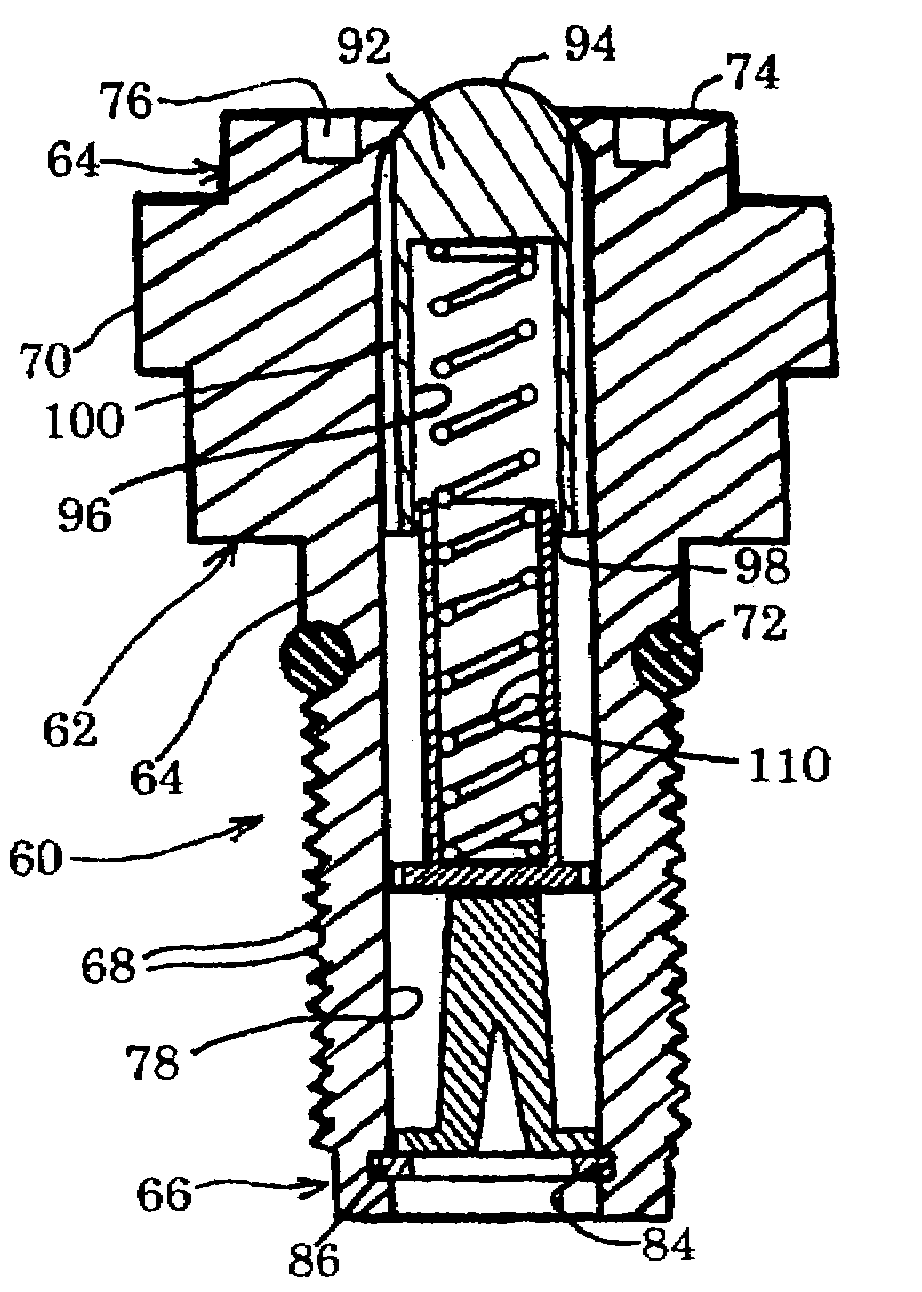
[0077]Referring now to FIGS. 15-17, the fluid flow control valve of the present invention is disclosed. This embodiment is preferably in the form of a valve member 118 that includes a housing 62 constructed substantially identical to the prior embodiment of FIGS. 5-14. The housing 62 of this embodiment includes the upper or inlet end portion 64, an bottom or outlet end portion 66, a central bore 78, an annular inner lip 82 forming a narrowed end opening 80, and an exit opening 116. In this particular embodiment, the bias mechanism is also a coil spring 102. However, in this embodiment, the lower end portion 106 of the spring 102 is positioned around the filter member 114 against the base 115 thereof. There is no spring containment sleeve in this embodiment. The upper end portion 104 of the spring 102 is engaged with a pressure responsive element 88 as in the prior embodiment.

[0078]In this particular embodiment, the pressure responsive element 88 is preferably in the form of a solid ...

third embodiment

[0079]Referring now to FIGS. 18-20, the fluid flow control valve of the present invention is disclosed. This embodiment is preferably in the form of a valve member 132 that includes a housing 62 constructed substantially identical to the prior embodiments for FIGS. 5-17. The housing 62 of this embodiment includes the upper or inlet end portion 64, an bottom or outlet end portion 66, a central bore 78, an annular inner lip 82 forming a narrowed end opening 80, and an exit opening 116. In this embodiment, the bias mechanism is also a coil spring 102, and the lower end portion 106 of the spring 102 is positioned to be engaged within a spring containment sleeve 108 having a base portion 110 with notches 112, as in the embodiment of FIGS. 5-14. In this particular embodiment, however, the filter member 134 is substantially flat as opposed to the conical shape of the prior embodiments, the c-clip 86 holding all the internal components of the valve 132 in place within the bore 78. The upper...

fourth embodiment

[0081]Referring now to FIGS. 21-23, the fluid flow control valve of the present invention is disclosed. This particular embodiment includes a valve member 150 that is substantially identical to the valve member 118 of FIGS. 15-17 except for the construction of the pressure responsive element 88. In this embodiment as with all the embodiments, like numerals designate like parts. In this particular embodiment, the pressure responsive element 88 is in the form of a solid piston head 152 having an upper curved surface 154 similar to the surface 122 of the embodiment of FIGS. 15-17. A plurality of axially aligned and spaced longitudinal grooves 156 form fluid channeling elements and operate in the same manner as the grooves 124 of the prior embodiment. However, the bottom portion 158 of the piston head 152 includes an annular, radially recessed groove 160 which forms a radial shoulder 162. The upper end portion 104 of the spring 102 is sized to surround the shoulder 162 and seat in the g...


PUM


Abstract

A fluid flow control valve is disclosed. This valve includes a housing which defines a central passageway having fluid inlet and fluid outlet openings. A pressure responsive element is disposed within the passageway for selectively opening and closing the inlet opening to fluid flow in response to fluid pressure exerted thereon at the inlet opening. A mechanism is provided within the passageway for exerting a bias force against the pressure responsive element which is sufficient to close the inlet opening to fluid flow absent a pre-established level of fluid pressure exerted on the pressure responsive element. A fluid filter element is also disposed within the passageway; and a retainer device is positioned for removably securing the filter element within the passageway.

Description

RELATED APPLICATIONS[0001]This application is a continuation of U.S. patent application Ser. No. 10 / 265,533, filed Oct. 3, 2002 now U.S. Pat. No. 6,901,958, titled FLUID FLOW CONTROL VALVE, which is a continuation of U.S. patent application Ser. No. 09 / 872,130, filed Jun. 1, 2001 now U.S. Pat. No. 6,601,609, titled FLUID FLOW CONTROL VALVE. The entire contents of these prior applications Ser. Nos. 10 / 265,533 and 09 / 872,130 are hereby incorporated by reference herein and made a part of this specification.BACKGROUND OF THE INVENTION[0002]1. Field of the Invention[0003]The present invention relates generally to fluid flow control and regulation devices and, more particularly, to one-way flow control devices and valves for pressurized fluids, especially gas. Specifically, the present invention relates to such flow control devices particularly adaptable as inlet valves for first and second stage regulator members used in scuba diving units to prevent the entry of water and other contamin...

Claims


Application Information

Patent Timeline
Patent Type & Authority Patents(United States)
IPC IPC(8): F16K15/02A62B9/02B63C11/22F16K15/18
CPCB63C11/2209B63C11/2227F16K1/303F16K1/307F16K1/308F16K15/026F16K15/033F16K15/044F16K15/18G05D7/0133A62B9/02Y10T137/7929Y10T137/88054Y10T137/7931Y10T137/7837Y10T137/7795F16K15/02F16K15/182F16K15/063
Inventor TAYLOR, SHANE S.
Owner HO UNDERWATER ACQUISITION LLC
Why Eureka
Try Eureka