Switching device

a switching device and packet switching technology, applied in data switching networks, frequency-division multiplexes, instruments, etc., can solve the problems of large aggregate bandwidth, rapid unimplementability with increasing the number of line cards, instantaneous congestion of output line cards, etc., to achieve easy fault detection and recovery features, less storage, and minimal reordering of cells

Inactive Publication Date: 2008-03-11
JUMIPER NETWORKS INC
View PDF13 Cites 48 Cited by
  • Summary
  • Abstract
  • Description
  • Claims
  • Application Information

AI Technical Summary

Benefits of technology

[0025]Among the advantages of the invention are one or more of the following. An inexpensive fabric flow control mechanism is provided by incorporating requests and grants in a data transfer algorithm. The invention provides a request-grant protocol for forwarding packets through a switching fabric and provides an inexpensive means for storing requests and grants in the switching fabric. Data load can be distributed equally across the switching fabric. The algorithms adopted guarantee fairness, i.e., each contender gets an equal share of bandwidth by providing a queue for each possible combination of source and destination.
[0026]The invention minimizes reordering of cells (received at the destinations) and allows for easy fault detection and recovery features. The algorithms require minimal queue storage in the switching fabric. The switching fabric provides fairness using a queue organization that requires less storage than a conventional router.

Problems solved by technology

Given this chaotic behavior, routers can experience instantaneous congestion at their output line cards independent of their internal design.
A key problem in designing routers is to make them scale to a large aggregate bandwidth.
In the central switch approach, the problem of building a scalable router reduces to a problem of building a scalable switch fabric.
A centralized controller works well for a relatively small router, however it rapidly becomes unimplementable with increases in the number of line cards.
The storage and processing requirements of the central controller grow at least as the square of the number of line cards, making this approach of limited utility in scaling routers to a large size.

Method used


Image

  • Switching device
  • Switching device
  • Switching device

Examples


Embodiment Construction

[0057]The present invention provides an efficient switching device and methodology for routing packets through a network. A number of terms are used herein to describe network transmissions and related structures and processes.

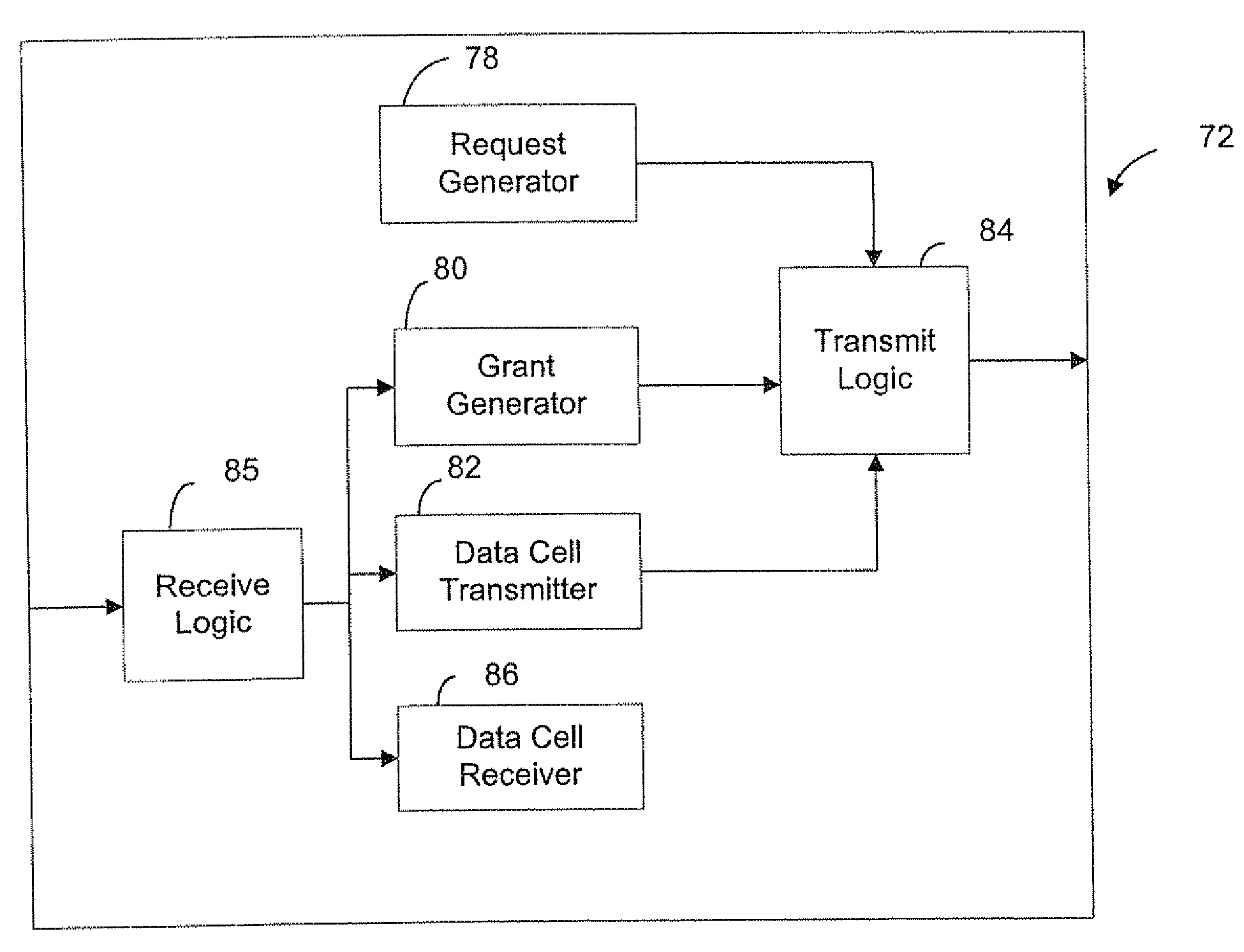
[0058]“Data cell” or “cell” refer to a smallest block of data that is passed through a switching device. The data cell includes a header portion and a data portion. Each packet received on an input port is divided in to one or more fixed length cells. “Cell data” refers to data contained within a data portion of a cell. “Data transfer unit” refers to a cell that includes request and grant information along with cell data.

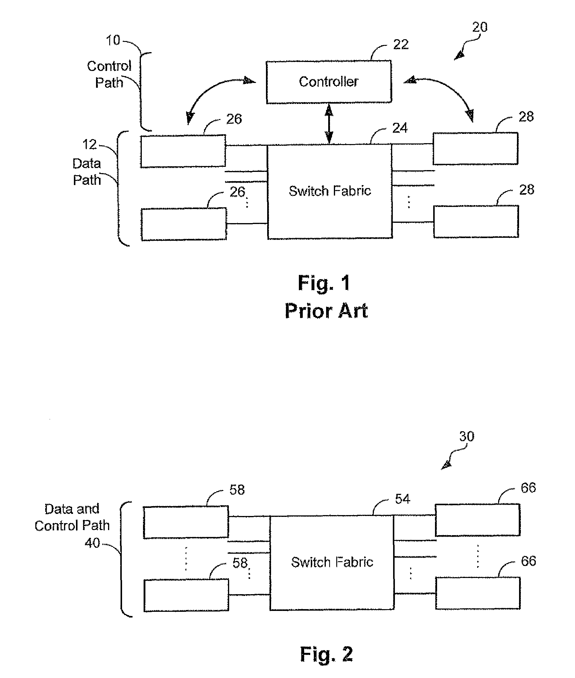
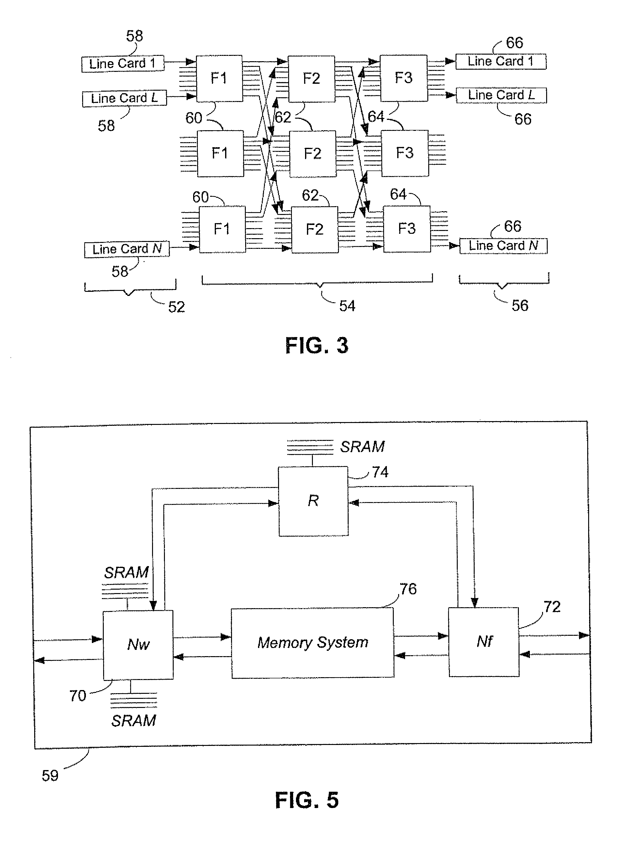
[0059]Referring to FIG. 2, a switching device 30 includes a data path 40. Data path 40 includes a switch fabric 54, source line cards 58 and destination line cards 66. The data path provides paths for transferring packets from source line cards 58 to destination line cards 66. Unlike a conventional router, the present invention does not requir...


PUM


Abstract

A switching device in a network system for transferring data includes one or more source line cards, one or more destination line cards and a switching fabric coupled to the source line cards and the destination line cards to enable data communication between any source line card and destination line card. Each source line card includes a request generator to generate a request signal to be transmitted in order to obtain an authorization to transmit data. Each destination line card includes a grant generator to generate and send back a grant signal to the source line card in response to the request signal received at the destination line card to authorize the source line card to transmit a data cell to the destination line card.

Description

RELATED APPLICATION[0001]This application is a continuation of U.S. patent application Ser. No. 09 / 448,124 filed Nov. 24, 1999 now U.S. Pat. No. 7,102,999 which is incorporated herein by reference.BACKGROUND[0002]The present invention relates generally to data routing systems, and more particularly to a method and apparatus for routing packets through a network.[0003]In a packet switched network, a router is a switching device that receives a packet on an input line card and switches it to an output line card. Routers perform this switching function by evaluating header information at the beginning of the packet in order to determine the proper output line card for that packet. A line card can include both input ports and output ports. That is, each line card can be configured to both transmit and receive packets.[0004]Packet traffic received by a router in the middle of a network has no predictable patterns. Packets can flow from any input line card to any output line card. Given t...

Claims


Application Information

Patent Timeline
Patent Type & Authority Patents(United States)
IPC IPC(8): G06F11/00H04J3/14H04L12/56H04L49/111
CPCH04L49/45H04L49/30H04Q3/54591H04L49/10H04L49/1523H04L49/3072H04L49/506H04L49/115H04L49/112H04L49/111H04L45/72H04L49/101
Inventor SINDHU, PRADEEPLACROUTE, PHILIPPE G.TUCKER, MATTHEW A.WEISBLOOM, JOHN D.WINTERS, DAVID B.
Owner JUMIPER NETWORKS INC
Why Eureka
Try Eureka