Connection of internally lined pipelines

Active Publication Date: 2008-03-18
TECH FRANCE SA +1
View PDF10 Cites 21 Cited by
  • Summary
  • Abstract
  • Description
  • Claims
  • Application Information

AI Technical Summary

Benefits of technology

[0013]A primary object of the present invention is to provide a method of joining lined pipelines, and an insert for use in said method, which give a simple a

Problems solved by technology

This method is complicated to implement and takes time.
Also, it cannot provide gas drainage grooves extending across the join.
However, the arrangement disclosed in this document has the disadvantage that the location of the ceramic ring can vary; this is because the liners and the insert are typically joined under tension, and when abutting the external pipe

Method used


Image

  • Connection of internally lined pipelines
  • Connection of internally lined pipelines
  • Connection of internally lined pipelines

Examples


Embodiment Construction

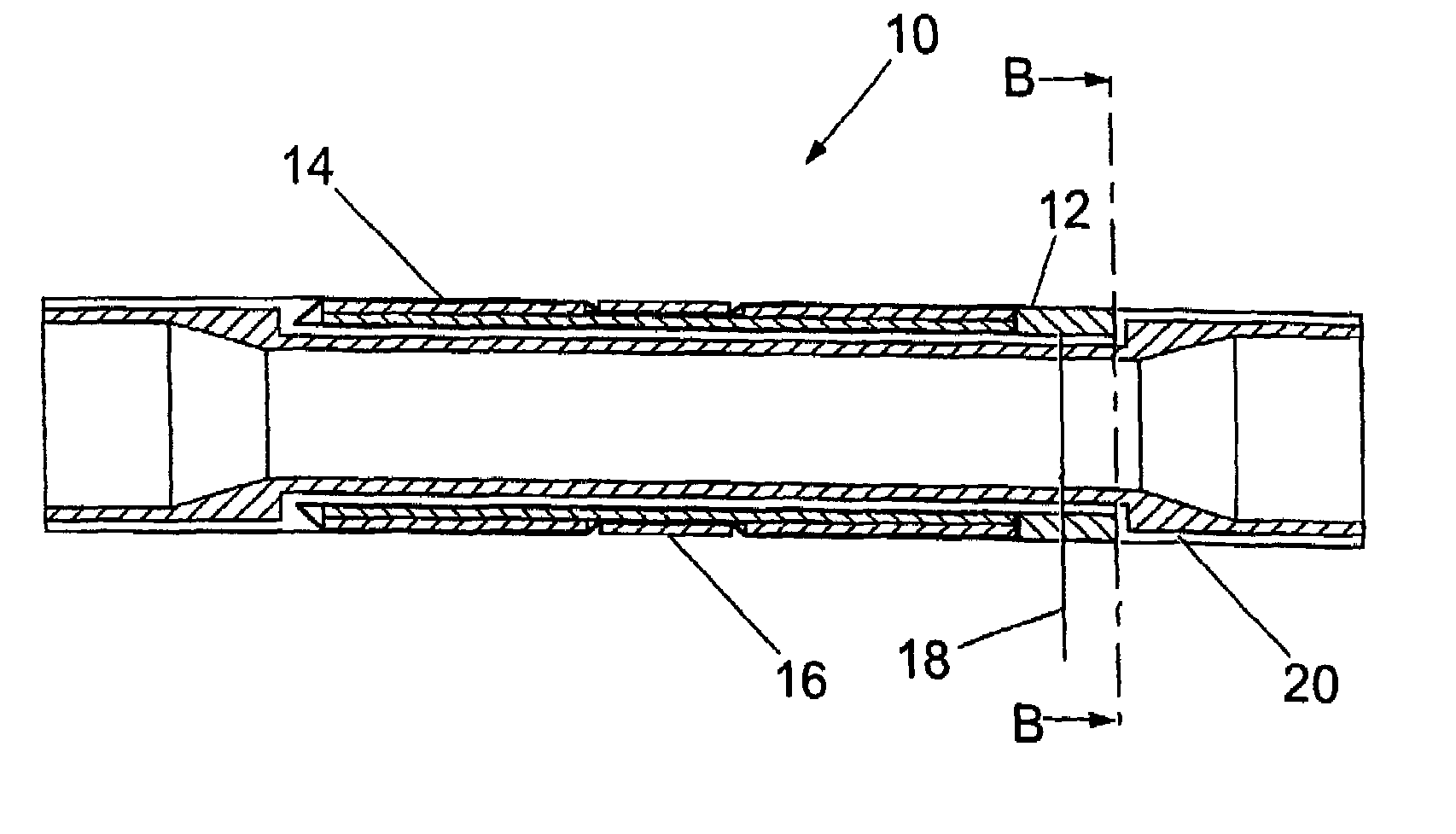
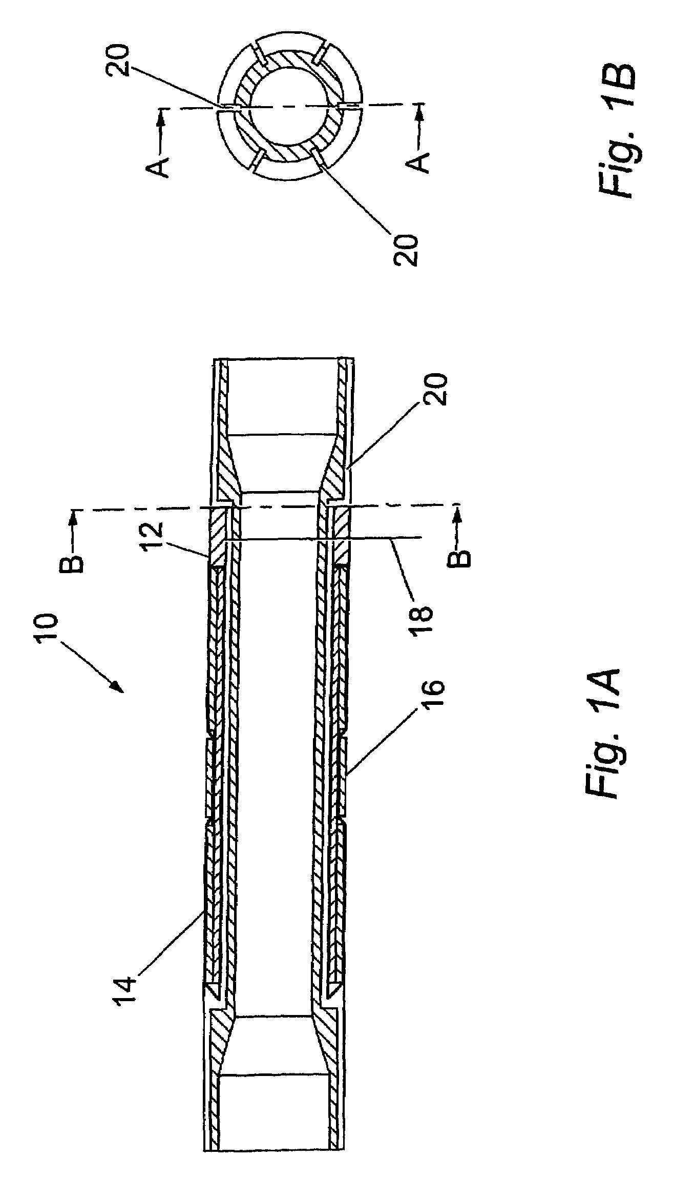
[0039]Referring to FIGS. 1 to 3, an insert 10 for use in joining two lengths of pipe comprises an inner tubular member 12 having a central recess in which is received a sleeve 14. The sleeve 14 in turn has a peripheral annular groove in which is received a non-metallic heat resistant element such as a ceramic ring 16. The insert 10 is intended for use in joining pipes having plastic liners, for example of high density polyethylene (HDPE) or fluorocarbon polymer, and the tubular member 12 is formed of a material matching the liners. One suitable material for the tubular member 12 is “Rilsan” polyamide by Atofina. The ceramic ring may, for example, be of Gullco “Katbac” material.

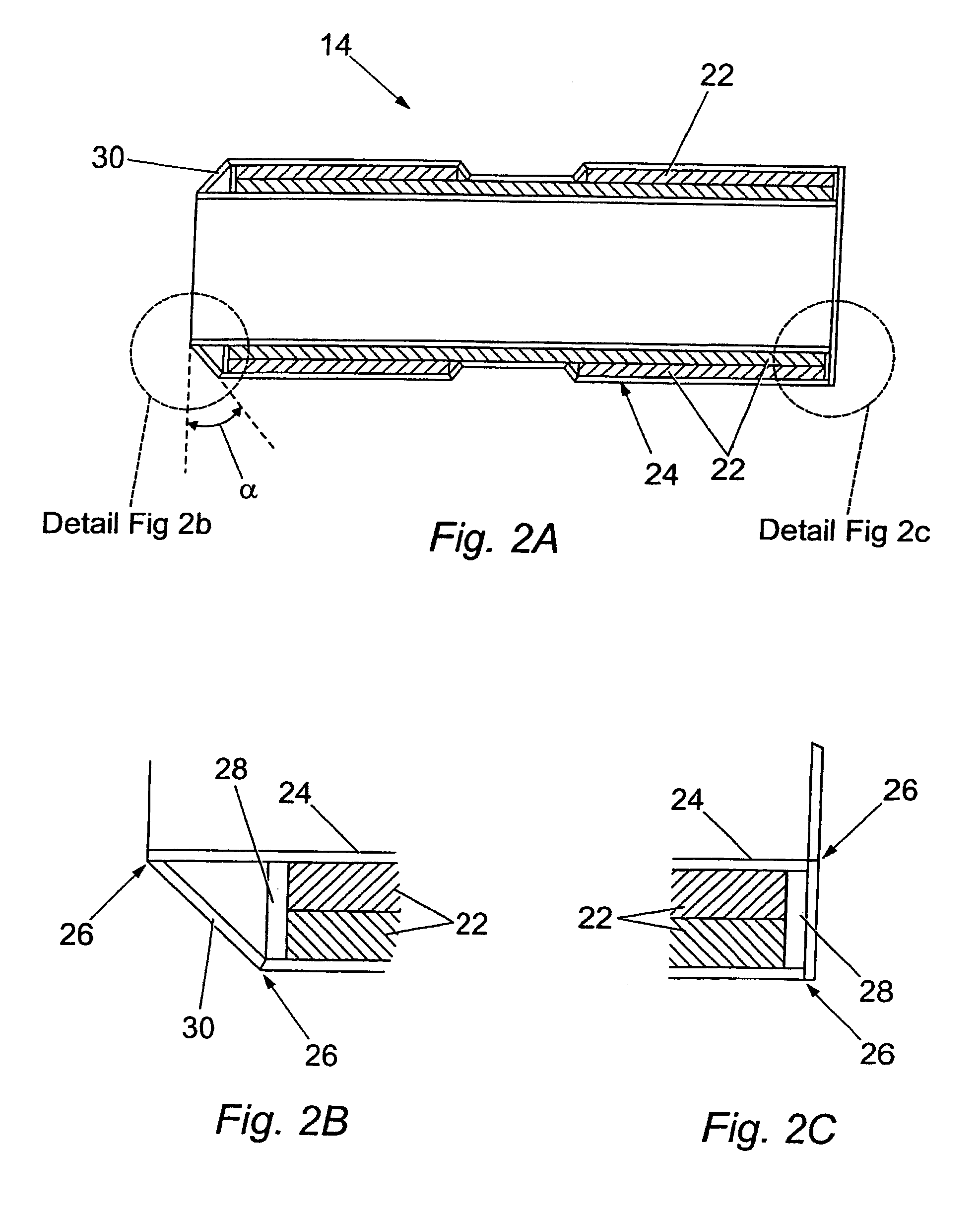
[0040]As best seen in FIG. 2, the sleeve 14 comprises a thermal insulation material 22 enclosed within a sheath 24. The insulation material is preferably a compressible material, for example a compressible microporous or insulation foam; one example is a microporous foam having a density of 160-210 kg / m3. The ...


PUM

PropertyMeasurementUnit
Temperatureaaaaaaaaaa
Lengthaaaaaaaaaa
Thicknessaaaaaaaaaa

Abstract

An insert for use in connecting two lengths of pipe, each having a plastic liner. The insert consists of an inner tubular member of plastics material for connection at either end to the plastic liners of two pipe lengths, an insulating sleeve surrounding a central portion of the inner tubular member and a ring of heat-resistant material overlying a part of the insulating sleeve to be positioned, when in use, beneath a location at which the pipe length is butt welded, wherein the insulating sleeve includes an insulating material which is at least partially enclosed with a sheath, such that the sheath can be mechanically connected to the interior of one pipe length.

Description

BACKGROUND OF THE INVENTION[0001]1. Field of the Invention[0002]This invention relates to pipelines which are lined with a plastics material.[0003]Pipelines are constructed by first forming lengths or “stalks” of pipe, and subsequently joining the stalks together. The stalks may be joined in the field for a land-based pipeline. for a subsea pipeline, the stalks may be joined on a lay barge, or may be joined while the pipe is being reeled onto a reel laying vessel.[0004]In many applications a metal, typically a steel, pipeline must be lined with a plastic liner in order to prevent corrosion of the internal surface of the pipe because of the nature of the fluid to be transported and on conditions of use such as pressure and temperature. When connecting stalks of lined pipe together, it is necessary to ensure that the corrosion protection provided by the liner is continuous across the connection.[0005]In onshore use, it is common to connect together stalks of pipe by flanged connection...

Claims


Application Information

Patent Timeline
IPC IPC(8): F16L11/12F16L13/02
CPCF16L13/0263Y10T29/53917
Inventor HOWARD, BRETT PATRICKTOUGH, GORDON
Owner TECH FRANCE SA
Why Eureka
Try Eureka