Regulated switch driving scheme in switched-capacitor amplifiers with opamp-sharing

Active Publication Date: 2008-03-18
NAT SEMICON CORP
View PDF3 Cites 34 Cited by
  • Summary
  • Abstract
  • Description
  • Claims
  • Application Information

AI Technical Summary

Problems solved by technology

Although the opamp sharing technique shown in FIG. 4 can significantly reduce the power consumption, it brings extra design complexity to the ADC, which becomes a limiting factor in high speed and/or high resolution ADC design.
Indeed, the additional switches M3 and M4 pose great challenges to the design at high ADC speed (e.g. 170 MS/s).
The switches not only introduce extra series resistance that slows down the opamp settling, but also cause extra charge injection errors to the conversion, resulting in larger offset and inferior linearity.
Furthermore, further performance degradation is observed with power supply variations.
Moreover, there is a speed and accuracy trade-off when choosing the switch size for switches M3 and M4.
While a large switch size leads to low series re

Method used


Image

  • Regulated switch driving scheme in switched-capacitor amplifiers with opamp-sharing
  • Regulated switch driving scheme in switched-capacitor amplifiers with opamp-sharing
  • Regulated switch driving scheme in switched-capacitor amplifiers with opamp-sharing

Examples


Embodiment Construction

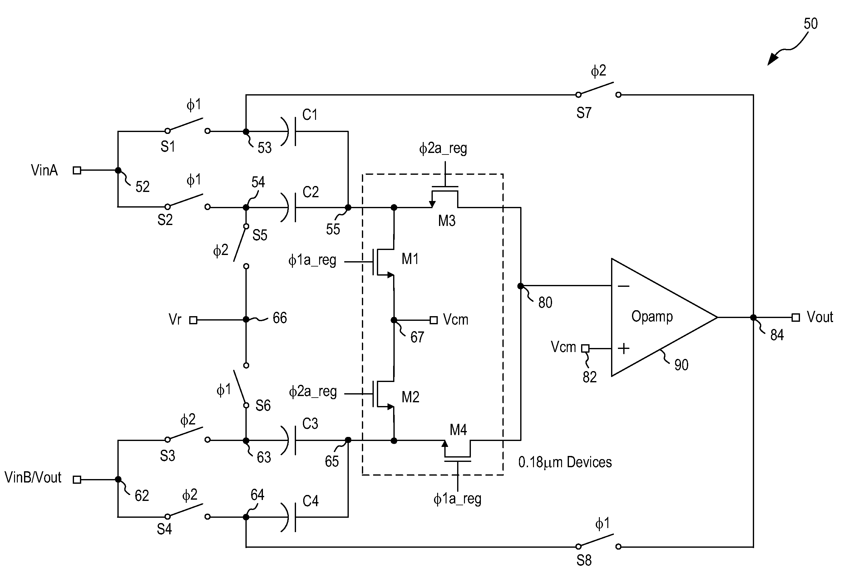
[0016]In accordance with the principles of the present invention, a switched-capacitor amplifier circuit configured in an opamp-sharing scheme implements a regulated switch driving scheme where a regulated power supply voltage is provided to drive a set of input switches coupling the sampling capacitors to an input terminal of the opamp. The regulated power supply voltage ensures that the set of input switches are driven at the optimal operating point and are isolated from power supply and process variations. By using a regulated power supply voltage to drive the set of input switches, the switched-capacitor amplifier circuit can realize effective opamp-sharing while ensuring high speed of operation and high accuracy in the conversion results.

[0017]The regulated switch driving scheme of the present invention is particularly advantageous in enabling the use of low voltage and high voltage devices to implement the switched-capacitor amplifier circuit. In one embodiment, the switched-c...


PUM


Abstract

A switched-capacitor amplifier circuit including first and second pairs of sampling capacitors for sampling a pair of input signals includes a voltage regulator coupled to receive a first reference voltage and generate a first regulated output voltage related to the first reference voltage and independent of a first power supply voltage; a clock signal generator generating first and second clock signals referenced to the first power supply voltage and third and fourth clock signals referenced to the first regulated output voltage; and a first set of switches coupling the bottom plates of the sampling capacitors to the amplifier, the first set of switches being controlled by the third and fourth clock signals. The circuit may further include a second set of switches coupling the top plates of the sampling capacitors to the input signals, the second set of switches being controlled by the first and second clock signals.

Description

FIELD OF THE INVENTION[0001]The invention relates to switched-capacitor amplifier circuits and, in particular, to a switched-capacitor amplifier circuit with opamp-sharing implementing a regulated switch driving scheme.DESCRIPTION OF THE RELATED ART[0002]Switched-Capacitor (SC) amplifiers are the most important building blocks in CMOS pipelined analog-to-digital-converters (ADCs). FIG. 1 illustrates one commonly used SC amplifier referred to as a multiplying-digital-to-analog-converter (MDAC). The MDAC of FIG. 1 is often applied in a pipelined ADC for providing fast and high resolution conversions. For instance, it is known to implement a 1.5b / stage pipelined ADC using the MDAC of FIG. 1.[0003]The MDAC of FIG. 1 operates under a non-overlapping clocking scheme as shown in FIG. 2. FIG. 3 illustrates an exemplary clock signal generator which can be used to generate the non-overlapping clock signals shown in FIG. 2. Referring to FIG. 1, SC amplifier 10 has two phase of operation: a sam...

Claims


Application Information

Patent Timeline
IPC IPC(8): H03F1/02
CPCH03F3/005
Inventor LI, JIPENGCOURCY, MATTHEWMANGANARO, GABRIELE
Owner NAT SEMICON CORP
Why Eureka
Try Eureka