
Two-mode radar level gauge system

a level gauge and radar technology, applied in the direction of antennas, liquid/fluent solid measurements, reradiation, etc., can solve the problems of insufficient accuracy of dielectric constant to obtain the desired high accuracy, gas above the surface of liquid reduces the velocity of microwaves, and the diameter may vary slightly, so as to achieve the same capacity and performance, simplify the feeding means, and the effect of cost-effective system

Active Publication Date: 2008-03-18
ROSEMOUNT TANK RADAR
View PDF12 Cites 36 Cited by
  • Summary
  • Abstract
  • Description
  • Claims
  • Application Information

AI Technical Summary

Benefits of technology

The system provides a cost-effective and reliable method for high accuracy liquid level gauging, independent of dielectric constant variations, by using two modes of propagation to calculate an accurate average pipe diameter and account for environmental conditions, ensuring custody transfer accuracy.

Problems solved by technology

However, for some applications the dielectric constant is not known sufficiently accurate to obtain a desired high accuracy.
However, a problem in such systems is that the gas above the surface of the liquid reduces the velocity of the microwaves.
The diameter of the steel pipe has enough stability (incl. a temperature correction) to be used as a standard but the initial determination of the diameter might present a problem including the fact that the diameter may vary slightly (say + / −0.5%) along the pipe.
Thus, an exact estimation of the diameter is difficult.
Such large discrepancy is in many applications, such as in custody transfer (CTS) applications, not acceptable.
Different modes propagate with different speed, which makes it difficult to make measurements when several modes are present.
However, a problem with the solution taught by this document is that it requires a rather complex feeding system in the transmitter in order to provide the different modes of the microwave signals, which increases the system complexity, cost and difficulty of use.

Method used


Image

  • Two-mode radar level gauge system
  • Two-mode radar level gauge system
  • Two-mode radar level gauge system

Examples


Embodiment Construction

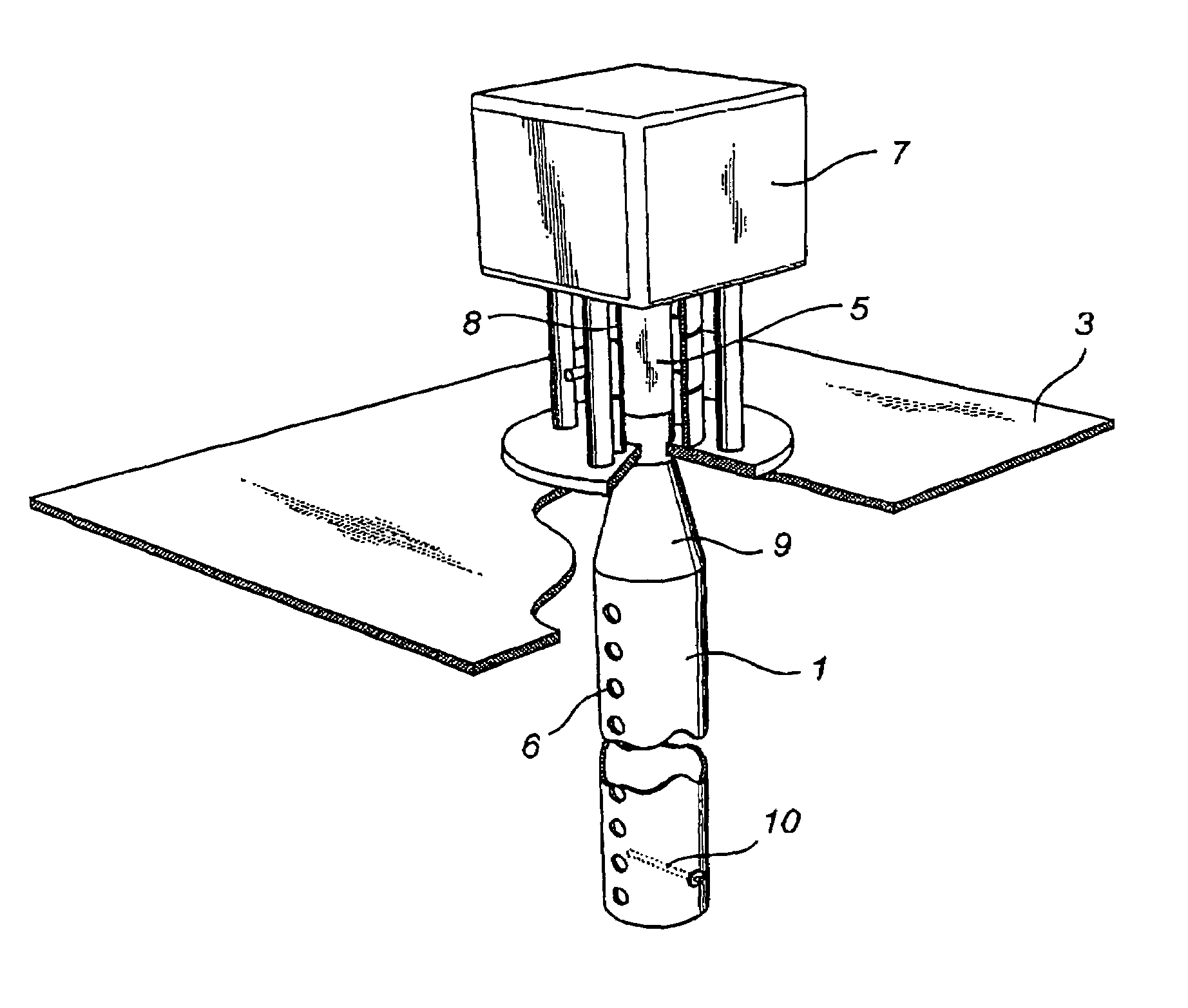
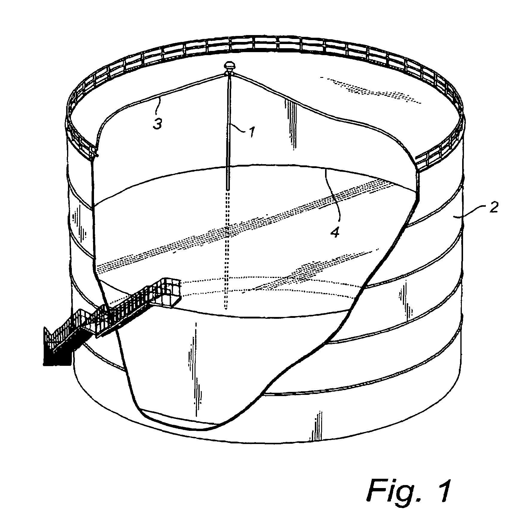
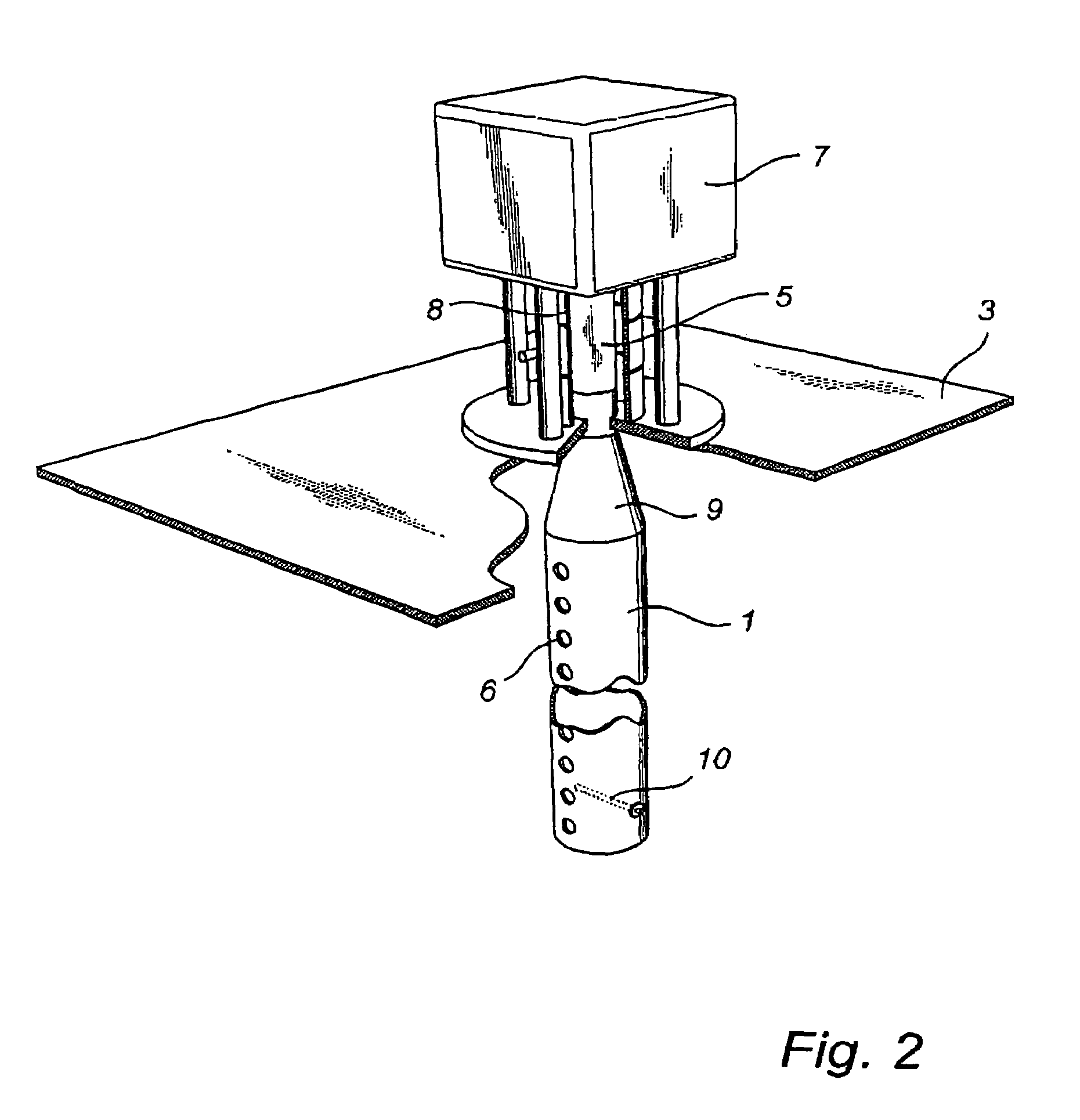
[0048]FIGS. 1 and 2 shows schematically a radar level gauge (RLG) system 1 according to an embodiment of the present invention. The system may be a frequency modulated continuous wave (FMCW) RLG system or a pulsed RLG system or any other type of distance measuring radar, but is preferably the former. The RLG system may have a capability of transmitting a microwave signal at a variable frequency, which is adjustable.

[0049]The RLG system comprises a waveguide 1, in the form of a substantially vertical tube or tube that is rigidly mounted in a container 2, the upper limitation or roof of which is designated by 3. The container contains a liquid 3, which may be a petroleum product, such as crude oil or a product manufactured from it, or a condensed gas, which is stored in the container at overpressure and / or cooled. Propane and butane are two typical gases stored as liquids.

[0050]The waveguide 1 is preferably of a metallic material to be capable of acting as a waveguide for microwaves a...


PUM


Abstract

A radar level gauge system for gauging the level of a filling material in a container is disclosed. The system comprises a waveguide extending towards the surface of said filling material; a transmitter for transmitting a microwave signal of a first mode of propagation in the waveguide; and a receiver for receiving the microwave signal reflected against the surface of the filling material and propagating back through the waveguide. Further, it comprises a processing circuitry for determining the filling level of the container based on the reflected microwave signal; and a transition element connecting the waveguide and the transmitter, wherein the transition element is configured to allow a part of the transmitted microwave signal to leak into a second mode of propagation. The first and second modes of propagation are within a frequency band which admits propagation of said microwave signal in the two different modes of propagation in the waveguide, wherein the receiver is arranged to receive the microwave signal in the at least two different modes of propagation.

Description

FIELD OF THE INVENTION[0001]The present invention relates generally to radar-based level gauging, and more specifically the invention relates to systems and methods for radar-based level gauging of the level of a filling material, and in particular a liquid, through a waveguide at high accuracy without prior knowledge of the exact gas composition and / or pressure above the surface of the filling material.TECHNICAL BACKGROUND[0002]Radar level gauge systems for measuring the level of a liquid or other filling materials in a container are well-known, and such a system generally comprises a transmitter for transmitting a microwave signal towards the surface of the liquid, a receiver for receiving the microwave signal reflected against the surface of the liquid, and a signal processing device for calculating the level of the liquid in the container from the propagation time of the transmitted and reflected microwave signal. Such device has become more and more important, particularly for ...

Claims


Application Information

Patent Timeline
Patent Type & Authority Patents(United States)
IPC IPC(8): G01S13/08
CPCG01F23/284G01S7/4052H01Q15/14G01S7/4056H01Q1/225G01S13/88G01S2007/4082G01S7/4082G01S13/08G01F23/00
Inventor EDVARDSSON, OLOV
Owner ROSEMOUNT TANK RADAR
Learn More