

Wearable smart device
a smart device and wearable technology, applied in the direction of dielectric characteristics, conductive pattern formation, protective garments, etc., can solve the problems of high wear and tear, high cost, and inconvenient mass production of methods, etc., to achieve excellent repeating bending resistance and repeating twisting resistance, reduce conductivity, and the effect of same current capacity
- Summary
- Abstract
- Description
- Claims
- Application Information
AI Technical Summary
Benefits of technology
Problems solved by technology
Method used
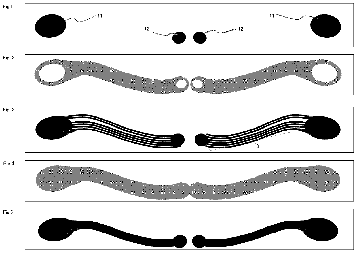
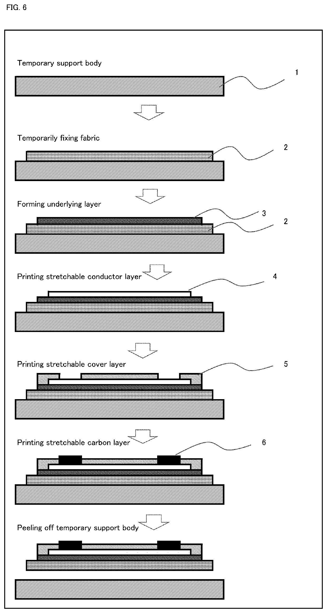
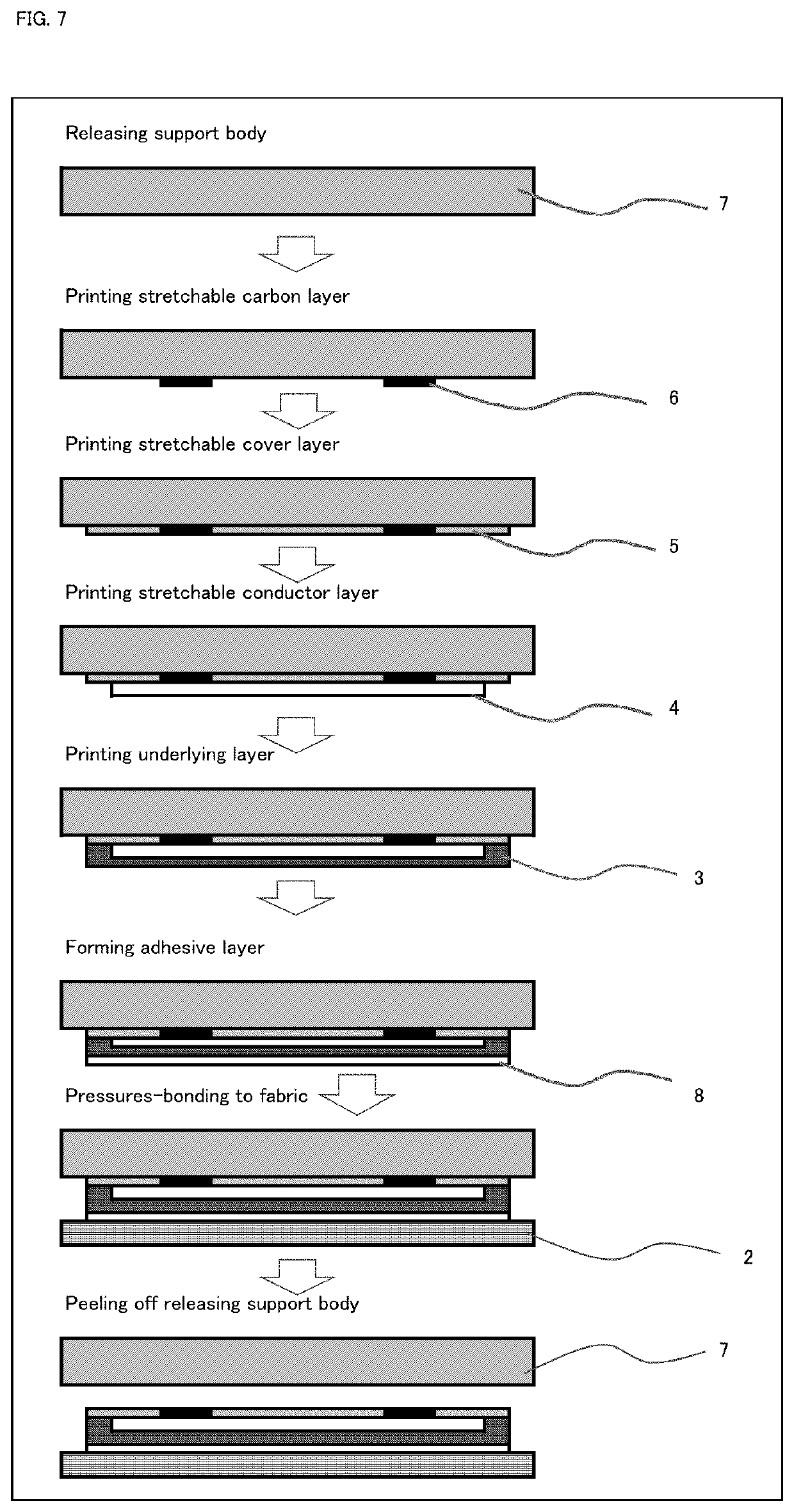
Image

Examples
production example 1
[0131]Into a stainless steel polymerization vessel with an internal volume of 3 L equipped with a stirrer and a condenser for distillation were charged 69.8 parts by mass of terephthalic acid, 93.0 parts by mass of terephthalic acid, 55.9 parts by mass of ethylene glycol, and 62.5 parts by mass of neopentyl glycol, followed by raising a temperature up to 235° C. over 3 hours under a pressure of 2.0 kgf / cm3, and water was distilled off to carry out esterification reaction. After the completion of the esterification reaction, 0.14 parts by mass of titanium tetrabutoxide was added, followed by stirring for 10 minutes. Then, an initial polymerization under a reduced pressure was conducted for 30 minutes until a pressure reached 650 Pa, the temperature was raised up to 255° C., and subsequently, a latter polymerization was further conducted under 130 Pa or less for 45 minutes. After the completion of polymerization, the pressure was adjusted to 1.0×10⁵ Pa with nitrogen and cooled to 200°...
production example 2
[0132]The following materials were put into a stainless steel reactor equipped with a stirrer and a water cooling jacket and gently stirred while keeping the bath temperature at 15° C. by flowing nitrogen.
[0133]
butadiene61parts by massacrylonitrile39parts by massdeionized water270parts by masssodium dodecylbenzenesulfonate0.5part by masssodium naphthalenesulfonate condensate2.5parts by masst-dodecyl mercaptan0.3part by masstriethanolamine0.2part by masssodium carbonate0.1part by mass
[0134]Next, an aqueous solution prepared by dissolving 0.3 part by mass of potassium persulfate in 19.7 parts by mass of deionized water was added dropwise into the reactor over 30 minutes, reaction was further continued for 20 hours, an aqueous solution prepared by dissolving 0.5 part by mass of hydroquinone in 19.5 parts by mass of deionized water was then added thereto, and an operation for stopping the polymerization reaction was carried out.
[0135]Next, in order to distill off unreacted monomers, the...
reference example 1
[Reference Example 1] Preparation of Stretchable Carbon Paste
[0139]A carbon paste for an electrode protective layer was prepared according to the composition as shown in Table 2.
[Reference Example 2] Stretchable Insulating Ink (Cover Coat Resin Ink, Ink for Forming an Underlying Layer)
[0140]A stretchable insulating ink was prepared according to the composition as shown in Table 2.
PUM
| Property | Measurement | Unit |
|---|---|---|
| elongation | aaaaa | aaaaa |
| width/thickness | aaaaa | aaaaa |
| width/thickness | aaaaa | aaaaa |
Abstract
Description
Claims
Application Information