Bandwidth enhanced self-injection locked DFB laser with narrow linewidth

Inactive Publication Date: 2008-03-18
HRL LAB
View PDF26 Cites 3 Cited by
  • Summary
  • Abstract
  • Description
  • Claims
  • Application Information

AI Technical Summary

Benefits of technology

[0002]Photonic beamforming techniques can be used for the optical control of phased arrays, for example in a space-based radar. A compact, directly modulated photonic transmitter that would exhibit large modulation bandwidths and low harmonic distortions is highly desirable in such an application.
[0003]Distributed feedback (DFB) lasers are key components for telecommunication networks and fiber based RF photonic systems. However, the bandwidth of commercial available DFB lasers is typically well below 10 GHz which will not be able to meet the needs of most near-future application. One way of improving the bandwidth to well beyond 10 GHz is to use external optical injection technique as theoretically predicted by J. Wang and G. Ybre and as experimentally demonstrated by X. J. Meng. Meng has reported the enhancement of bandwidth by a factor of 3.7 and reduction of second harmonic distortion by 10 dB. They also observed the narrowing of line-width in their experiments as well as the reduction of distortion products. See X. J. Meng, IEEE Trans. Microwave Theory &Technique, vol. 47, no. 7, pp 1172-1176 (1999).
[0004]However, the prior art technique requires the use of an external laser (e.g. a Ti-Sapphire laser) tuned to within 5-25 GHz of the slave DFB laser, to realize performance gains, which laser is bulky and adds expense. Furthermore, the use of two physically distinct lasers (as the master laser and slave laser) make their optimal conditions for injection locking highly vulnerable to environmental perturbations such as temperature variations.
[0005]The self-injection locking technique of the present invention offers the advantages of low cost and compactness combined with ruggedization in packaging. Most importantly, it offers thermal stability over the external injection technique reported by X. J

Problems solved by technology

However, the bandwidth of commercial available DFB lasers is typically well below 10 GHz which will not be able to meet the needs of most near-future application.
However, the prior art technique requires the use of an external laser (e.g. a Ti-Sapphire laser) tuned to within 5-25 GHz of the slave DFB

Method used


Image

  • Bandwidth enhanced self-injection locked DFB laser with narrow linewidth
  • Bandwidth enhanced self-injection locked DFB laser with narrow linewidth
  • Bandwidth enhanced self-injection locked DFB laser with narrow linewidth

Examples


Embodiment Construction

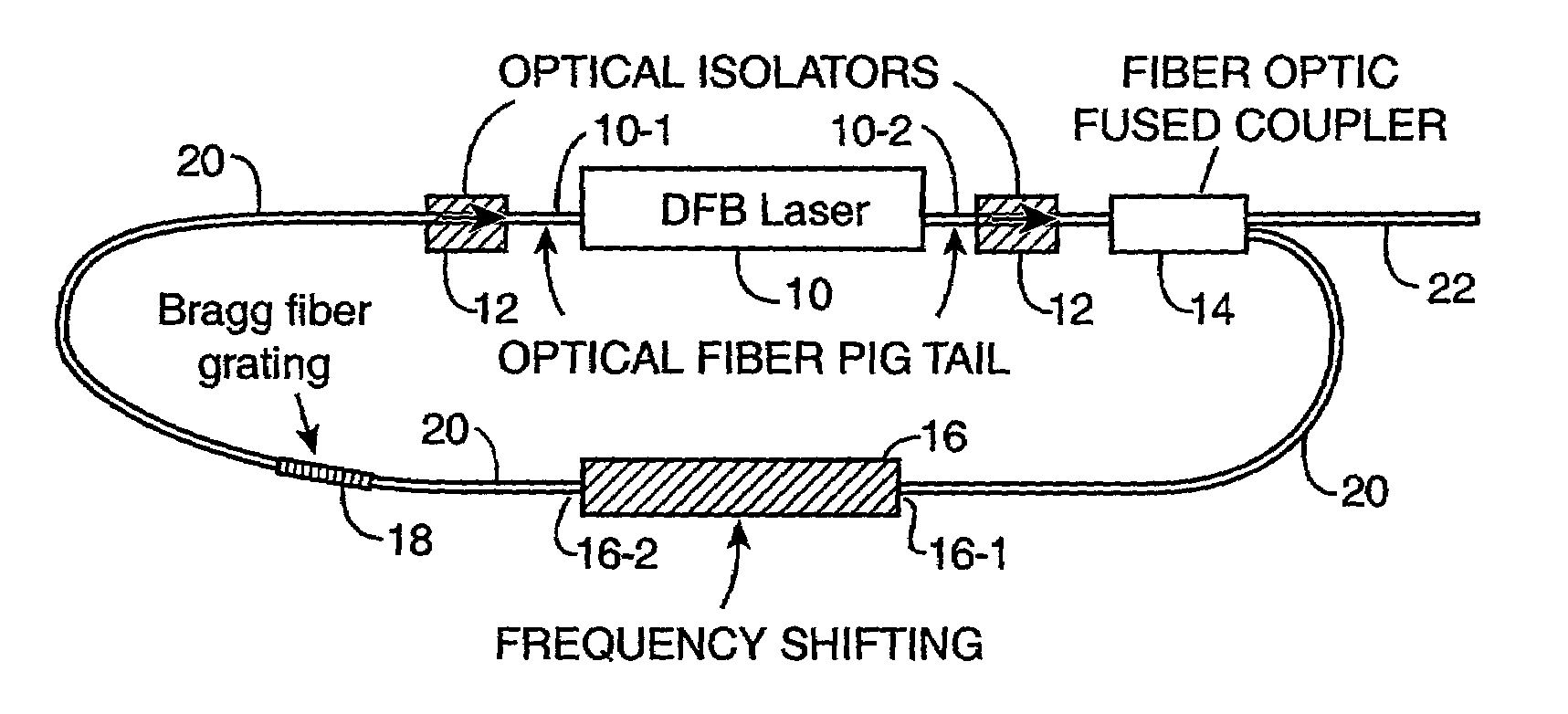
[0015]In accordance with the present invention, a self-injection system such as that shown in FIG. 1 is used to eliminate the need of using a bulky and expensive external laser. A distributed feedback (DFB) semiconductor laser is depicted by reference numeral 10. Other types of lasers than a DFB laser may be alternatively used provided that the laser is a single wavelength laser. For example, a DBR laser may be used in place of DFB laser 10. DFB lasers are preferred since they are readily available in the marketplace. A DFB laser typically has pigtails which can be conveniently used to connect it via optical isolators 12 to a fiber optical fused coupler 14 at the laser's output 10-2 and to a filter 18 at the laser's input 10-1. The optical isolators 12 are preferably used to eliminate undesirable reflective laser output from feeding back into the cavity of laser 10. Fiber optic cables 20 are preferably used to connect up these devices as shown in FIG. 1; however, those skilled in th...


PUM


Abstract

A laser system and method for self-injection locking. The system includes a laser having a laser output at a frequency ωo. An optical port provides a portion of the laser output at the port and a modulator, coupled to the port, is driven by a RF signal at a frequency ωm generates two sidebands at ωo±ωm. A filter passes one of the two sidebands; and an optical path couples an output of the filter to the laser for injection locking.

Description

TECHNICAL FIELD[0001]This invention relates to a self-injection locking technique for enhancing the modulation bandwidth of a distributed feedback (DFB) semiconductor laser. It will reduce simultaneously its harmonic distortion and linewidth.BACKGROUND AND ADVANTAGES OF THE INVENTION[0002]Photonic beamforming techniques can be used for the optical control of phased arrays, for example in a space-based radar. A compact, directly modulated photonic transmitter that would exhibit large modulation bandwidths and low harmonic distortions is highly desirable in such an application.[0003]Distributed feedback (DFB) lasers are key components for telecommunication networks and fiber based RF photonic systems. However, the bandwidth of commercial available DFB lasers is typically well below 10 GHz which will not be able to meet the needs of most near-future application. One way of improving the bandwidth to well beyond 10 GHz is to use external optical injection technique as theoretically pred...

Claims


Application Information

Patent Timeline
IPC IPC(8): H01S3/10G02F1/01H01S3/083H01S3/098H01S5/12H01S5/14
CPCH01S5/12H01S3/083H01S5/1071H01S5/146
Inventor HSU, TSUNG-YUANNG, WILLIEYAP, DANIEL
Owner HRL LAB
Why Eureka
Try Eureka