Tension sensing assembly

a technology of tension sensor and assembly, which is applied in the direction of instruments, pedestrian/occupant safety arrangements, force/torque/work measurement apparatus, etc., can solve the problems of high tension in the seat restraint system, large package size, and insufficient sensing capability of compression springs, so as to reduce the amount of parts, reduce the overall package size, and reduce the effect of tension sensing capability

Inactive Publication Date: 2008-03-25
AUTOLIV DEV AB
View PDF60 Cites 22 Cited by
  • Summary
  • Abstract
  • Description
  • Claims
  • Application Information

AI Technical Summary

Benefits of technology

[0008]One advantage of the present invention is that a new tension sensing assembly is provided for a seat restraint system in a vehicle. Another advantage of the present invention is that the tension sensing assembly may be mounted on a buckle or inboard side of the vehicle or an anchor or outboard side of the vehicle. Yet another advantage of the present invention is that the tension sensing assembly incorporates at least one tension spring that provides low tension sensing capability (0 to 30 lb.). Still another advantage of the present invention is that the tension sensing assembly is compatible with a buckle pretensioner. A further advantage of the present invention is that the tension sensing assembly provides a reduction in overall package size and reduces the amount of parts. Yet a further advantage of the present invention is that the tension sensing assembly has a reduced number of wire-harness breakouts and electrical connectors. Still a further advantage of the present invention is that the tension sensing assembly has reduced component, system, and material costs. Another advantage of t

Problems solved by technology

With this condition, there will be high tension in the seat restraint system.
However, these compression springs do not provide adequate sensing capability at low tension levels.
In addition, these tension sensors may exhibit rattle noise and have a relatively large package size.
Further,

Method used


Image

  • Tension sensing assembly
  • Tension sensing assembly
  • Tension sensing assembly

Examples


Embodiment Construction

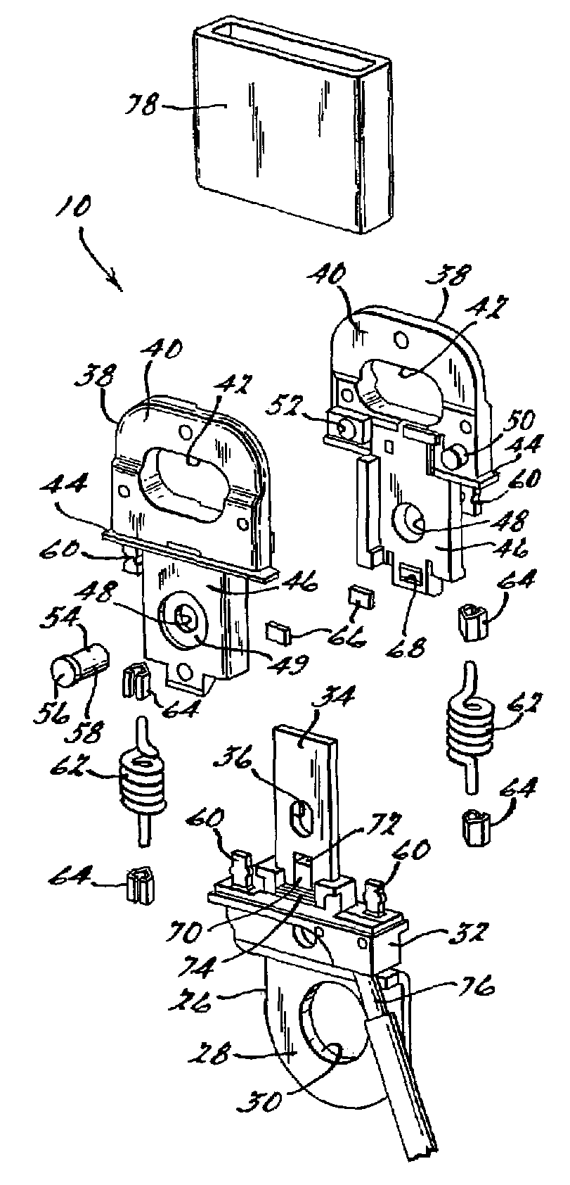
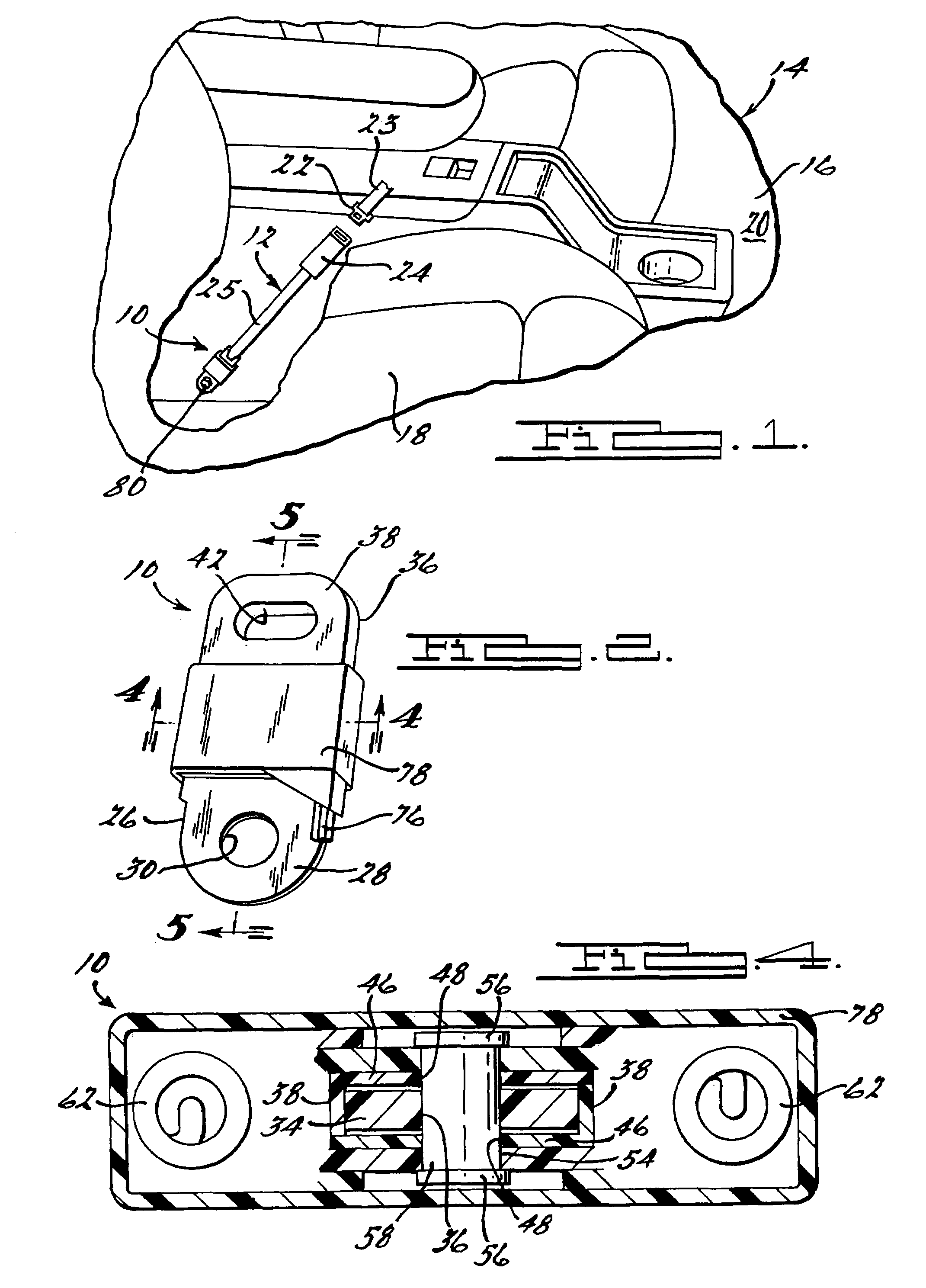
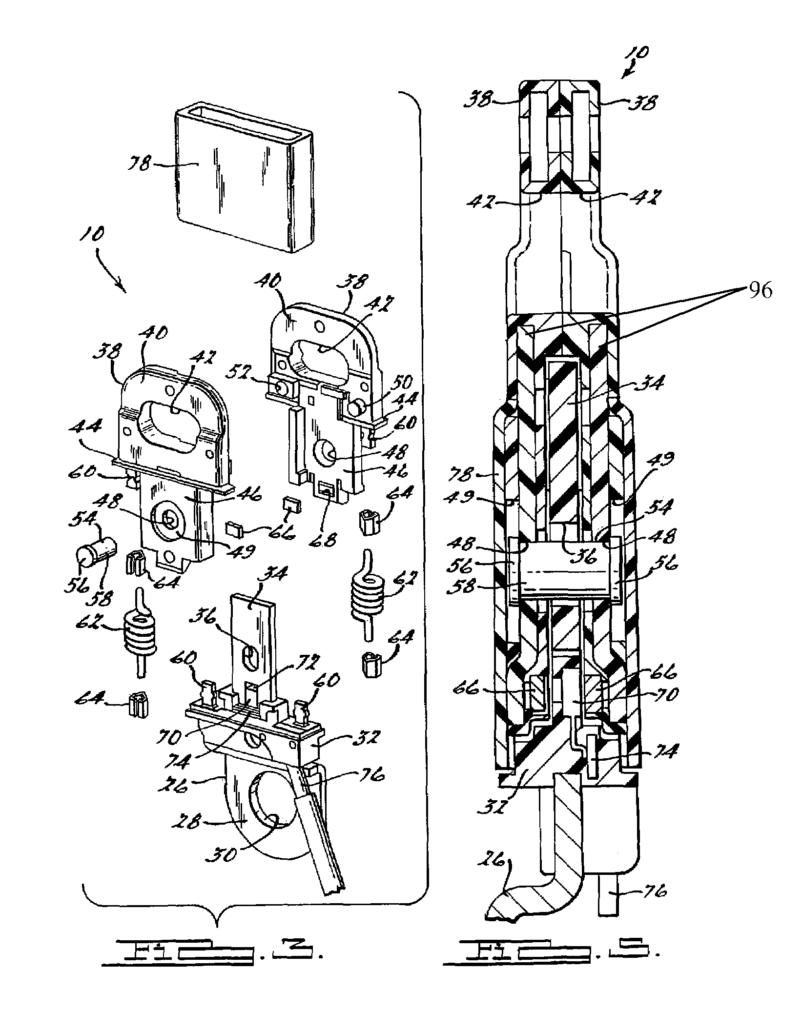
[0019]Referring to the drawings and in particular FIG. 1, one embodiment of a tension sensing assembly 10, according to the present invention, is shown for a seat restraint system, generally indicated at 12, in a vehicle (partially shown), generally indicated at 14. The vehicle 14 includes a vehicle body 16 and a seat 18 mounted by suitable means to vehicle structure such as a floorpan (not shown) in an occupant compartment 20 of the vehicle body 16. In this embodiment, the seat 18 is a front seat of the vehicle 14. It should be appreciated that the seat 18 could be a rear, second row, or third row seat for the vehicle 14.

[0020]Referring to FIG. 1, the vehicle 14 includes the seat restraint system 12 for restraining an occupant (not shown) in the seat 18. The seat restraint system 12 includes a latch tongue or plate 22 connected to belt webbing 23 at an end of either one of a lap belt, shoulder belt, or both which have another end connected to a retractor (not shown). The seat restr...


PUM


Abstract

A tension sensing assembly for a seat restraint system in a vehicle is provided. The tension sensing assembly comprises an anchor, a movable mechanism configured to be secured to a portion of a buckle, at least one magnet coupled to the movable mechanism, a Hall effect sensor coupled to the anchor, at least one tension spring secured to the anchor at a first end and the movable mechanism at a second end. The movable mechanism moves the at least one magnet relative to the Hall effect sensor to induce an output from the Hall effect sensor. The output indicates a tension level being applied to the tension sensing assembly.

Description

CROSS-REFERENCE TO RELATED APPLICATION(S)[0001]The present invention claims the priority date of copending U.S. Provisional Patent Application Ser. No. 60 / 464,761, filed Apr. 23, 2003.TECHNICAL FIELD[0002]The present invention relates generally to seat restraint systems for vehicles and, more particularly, to a tension sensing assembly for a seat restraint system in a vehicle.BACKGROUND OF THE INVENTION[0003]It is known to provide a seat restraint system such as a seat belt in a vehicle to restrain an occupant in a seat of the vehicle. In some vehicles, the seat restraint system may be a lap belt, a shoulder belt, or both. Typically, the lap belt and shoulder belt are connected together at one end. The seat restraint system includes a latch plate at the connected end. The seat restraint system also includes a buckle connected at one end by webbing or the like to vehicle structure. The buckle receives the latch plate to be buckled together. When the buckle and latch plate are buckled...

Claims


Application Information

Patent Timeline
IPC IPC(8): B60R22/00B60R21/01B60R21/015B60R22/18G01L5/10
CPCB60R22/18G01L5/103B60R21/0155B60R2022/1806
Inventor MALONEY, DAVID L.WOJTANEK, GUY A.GRIEB, GARY R.HLAVATY, DAVID G.WEBBER, JAMES L.MOURY, MICHAEL T.
Owner AUTOLIV DEV AB
Why Eureka
Try Eureka