Heart assist device utilising aortic deformation

a heart assist device and aortic deformation technology, applied in the field of counterpulsation heart assist devices, can solve the problems of no suggestion of how to deal with ischemic leg complications, and achieve the effect of reducing the risk of the patien

Active Publication Date: 2008-03-25
NUWELLIS INC
View PDF26 Cites 41 Cited by
  • Summary
  • Abstract
  • Description
  • Claims
  • Application Information

AI Technical Summary

Benefits of technology

[0020]In a third aspect, the present invention provides, in a heart assist device of the type which induces counterpulsation of an artery in the vasculature of a patient, the improvement comprising the application of a counterpulsation pressure to the exterior of the artery such that the artery is caused to compress substantially without stretching or bunching.
[0030]The heart assist device of the present invention allows, at least in preferred embodiments, partial unloading of the heart and augmenting of the cardiac output of the heart.
[0037]alternating the period of actuation with periods of deactivation of the motive means to periodically withdraw the fluid from the space in synchrony with the commencement of the systolic period, thereby allowing the portion of the aorta adjacent the device to return to normal interior volume.
[0043]The patch device is preferably attachable to the radially outer side of the ascending aorta. In one form, the patch device is attachable to the periphery of an opening in the ascending aorta formed by resecting a portion of the aorta. The membrane has a shape substantially replicating that of the interior surface of the resected portion of the aorta. The flexible membrane preferably also substantially replicates the shape of the interior of the patch device when the fluid is withdrawn from the space. It is believed that this design feature will reduce the incidence of thrombo-embolism by presenting, when deflated, a blood flow path without regions that would cause sluggish blood flow. The patch device is preferably in the shape of a truncated portion of a torus. The aorta is preferably resected along a line on the radially outer side, or passing through, the diameter of the mid point cross section of the aorta. The membrane, when the fluid is introduced into the space, is preferably expanded towards, but not abutting, the adjacent interior wall of the aorta.

Problems solved by technology

These devices suffer from the problem that there is a high risk of thrombo-embolism if the balloon remains in the vasculature for a prolonged period, which can lead to ischemic leg complications.
There is no suggestion of how to deal with the more complex issues that arise in placing the device into the ascending aorta which is curved along its length.

Method used


Image

  • Heart assist device utilising aortic deformation
  • Heart assist device utilising aortic deformation
  • Heart assist device utilising aortic deformation

Examples


Embodiment Construction

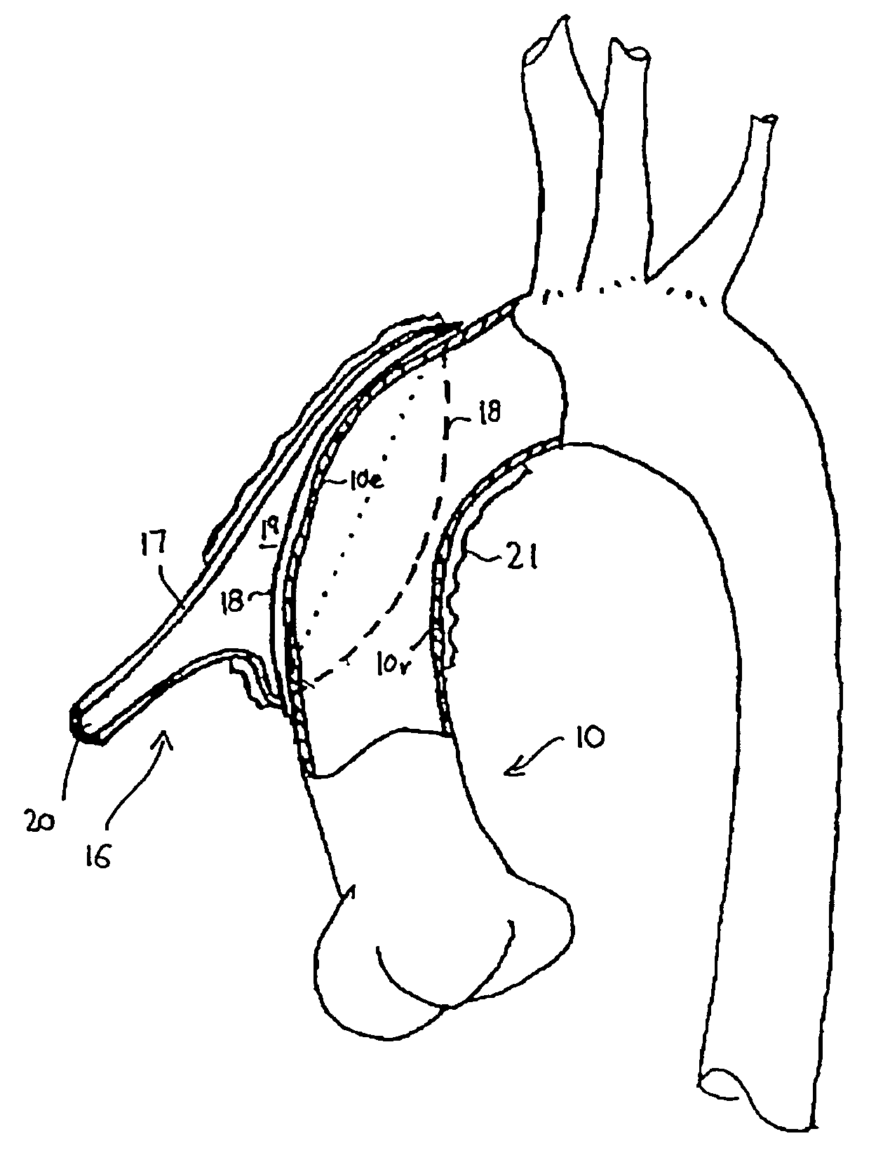
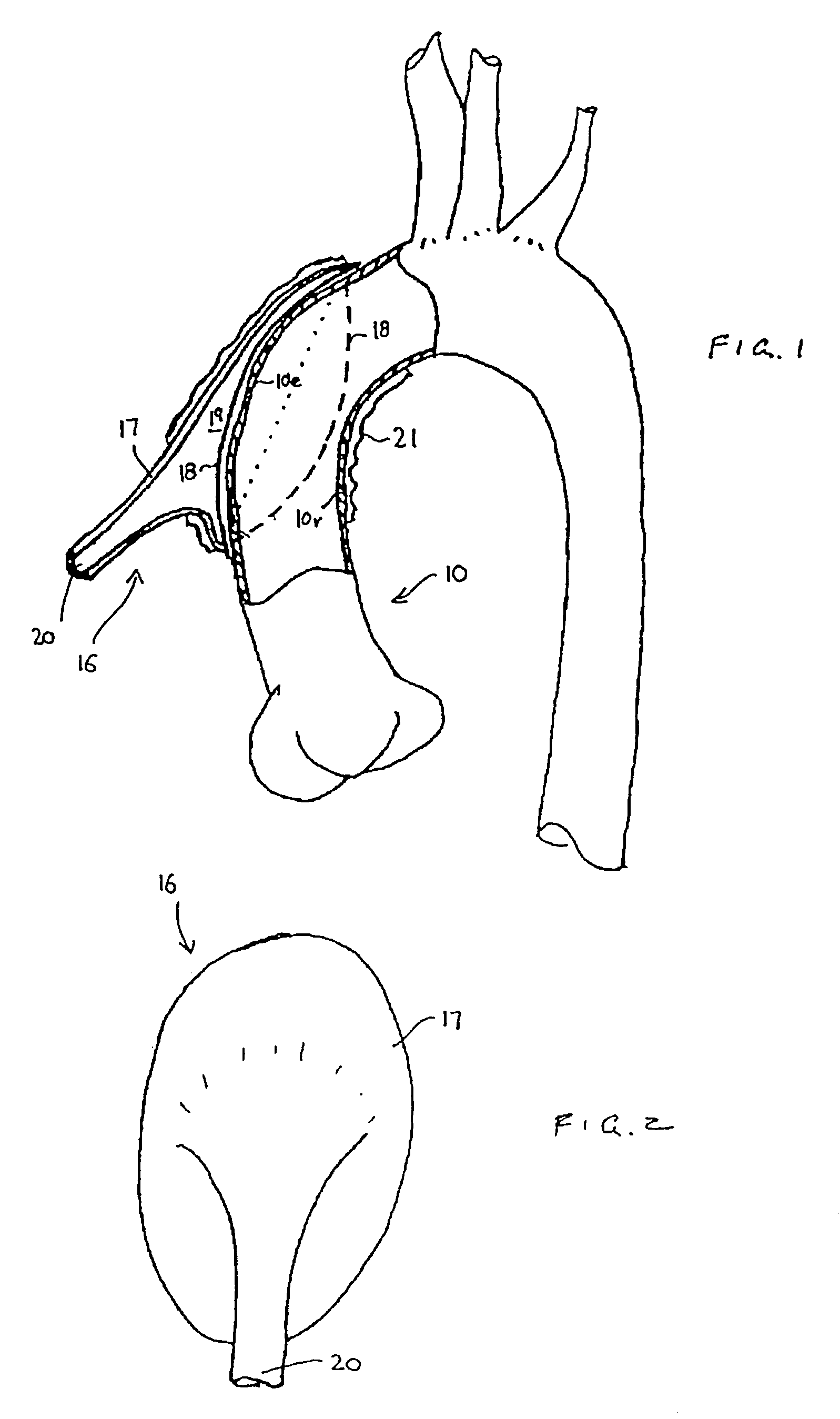
[0064]FIG. 1 is a schematic side view of an ascending aorta 10 and a heart assist device 16 in accordance with an embodiment of the invention. The device 16 has a relatively inelastic, preferably plastic, shell 17 and a flexible membrane 18 sealingly attached to the periphery of the shell 17. The membrane 18 defines an inflatable space 19 between it and the interior of the shell 17. The shell 17 also has an inlet / outlet port 20 which is adapted for connection to a motive means that can periodically introduce, and withdraw, a fluid (eg. a gas such as helium or a liquid such as a saline solution or an oil) to and from the space 19 in counter-pulsation with the patient's heart rhythm. The membrane 18 has a shape which is, when deflated, smoothly curved and facing directly inwardly towards the lumen of the ascending aorta 10.

[0065]A relatively inelastic wrap 21 is used to hold the device 16 in the position shown on the radially outer side of the ascending aorta 10.

[0066]The solid line 1...


PUM


Abstract

The present invention relates to providing counter-pulsation heart assist by deforming the aorta. In a preferred embodiment, the deformation pressure is applied by cyclically, preferably in synchrony with the diastolic period of the heart. The deformation pressure may be applied to the outer wall of the aorta or to a patch covering a resected opening in the wall of the aorta.

Description

RELATED INFORMATION[0001]This application claims priority to Australian Provisional Application No. 2002952691 filed on Nov. 15, 2002. The priority of this prior application is expressly claimed, and the disclosure of the provisional application is hereby incorporated by reference in its entirety.FIELD OF THE INVENTION[0002]The present invention relates generally to counterpulsation heart assist devices, systems and methods and, more particularly, to heart assist devices utilising aortic deformation and / or aortic resection.BACKGROUND OF THE INVENTION[0003]The concept of providing counter-pulsation support for the failing heart has been known since the pioneering work of Kantrowitz. Counter-pulsation causes displacement of a volume of a patient's blood in the patient's aorta while the patient's heart is dilating in diastole and after the aortic valve has closed. This assists to move blood around the patient's peripheral vasculature as well as into the coronary arteries. The timed vol...

Claims


Application Information

Patent Timeline
Patent Type & Authority Patents(United States)
IPC IPC(8): A61N1/362A61F2/04A61M1/10A61M1/12
CPCA61M1/107A61M1/1044A61M1/122A61M1/1005A61M1/1067A61M1/106A61M1/1072A61M60/869A61M60/274A61M60/148A61M60/161A61M60/289A61M60/569A61M60/468
Inventor PETERS, WILLIAM SUTTLEMILLER, SCOTT HUGHWATTERSON, PETER ANDREW
Owner NUWELLIS INC
Why Eureka
Try Eureka