Piezoelectric vibrator

a technology of vibrating device and piezoelectric technology, which is applied in the field of piezoelectric vibrating device, can solve the problems of reducing the ci value, reducing the shock resistance, and damage to electronic parts when manufacturing, and achieves the effect of great shock resistan

Inactive Publication Date: 2008-04-01
NIHON DEMPA KOGYO CO LTD
View PDF11 Cites 14 Cited by
  • Summary
  • Abstract
  • Description
  • Claims
  • Application Information

AI Technical Summary

Benefits of technology

[0014]Since the groove in the vibrating arm is divided into two in the longitudinal direction in the present invention, it is possible to obtain great shock resistance while crystal impedance (CI value) of the piezoelectric vibration is made small, as clear from a later-described experimental result.

Problems solved by technology

However, further decrease in the CI value has been required due to a request for efficiency of the power consumption in electronic parts using the quartz vibrator.
Furthermore, since the tuning fork type quartz vibrator described in the above-described Patent Document 1 has grooves on the tuning fork arms as described above, shock resistance is lessened when the quartz vibrator is miniaturized, and shock resistance against a drop or the like is low, which may possibly cause trouble such as damage when manufacturing electronic parts and so on.

Method used


Image

  • Piezoelectric vibrator
  • Piezoelectric vibrator
  • Piezoelectric vibrator

Examples


first embodiment

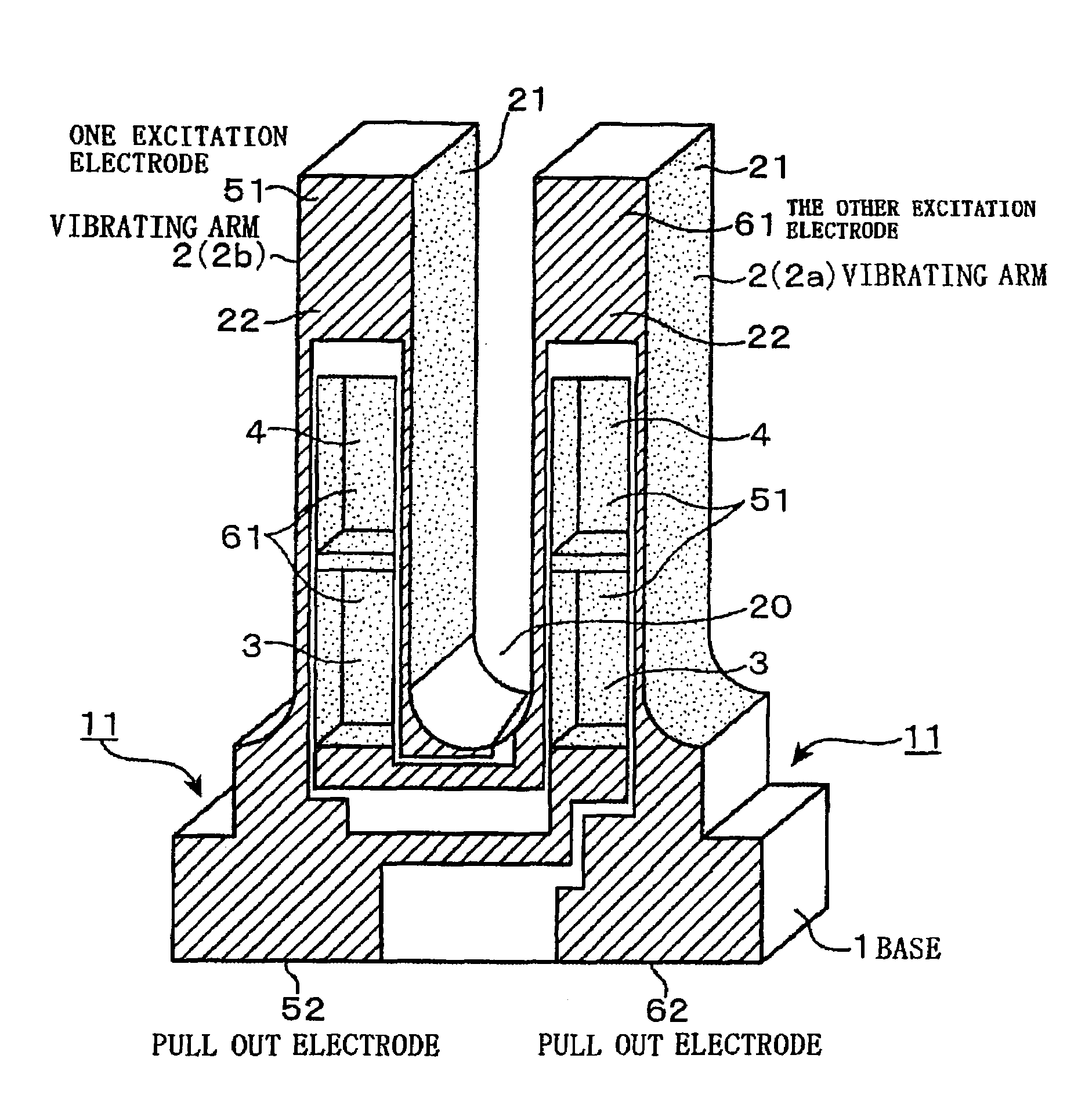
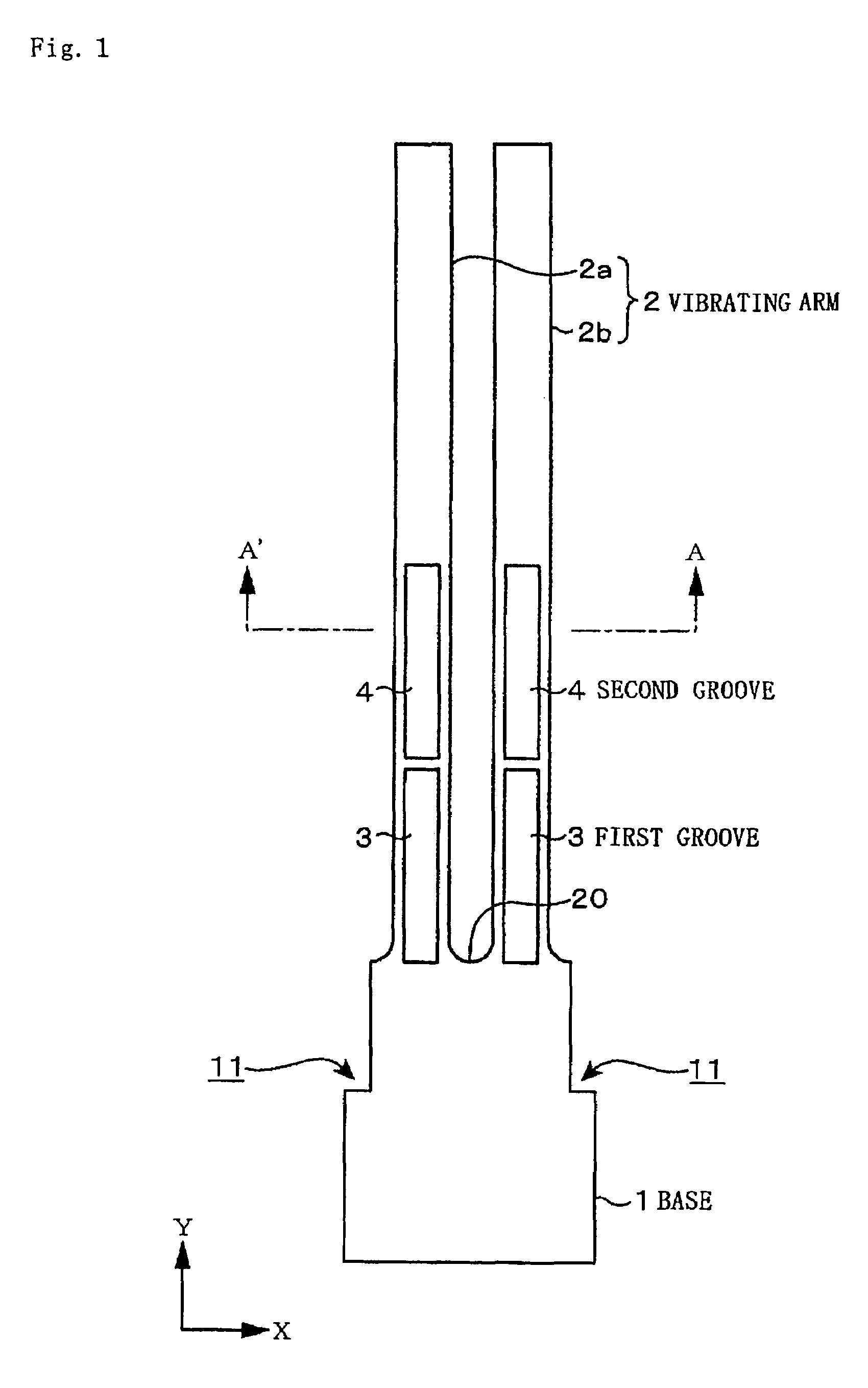
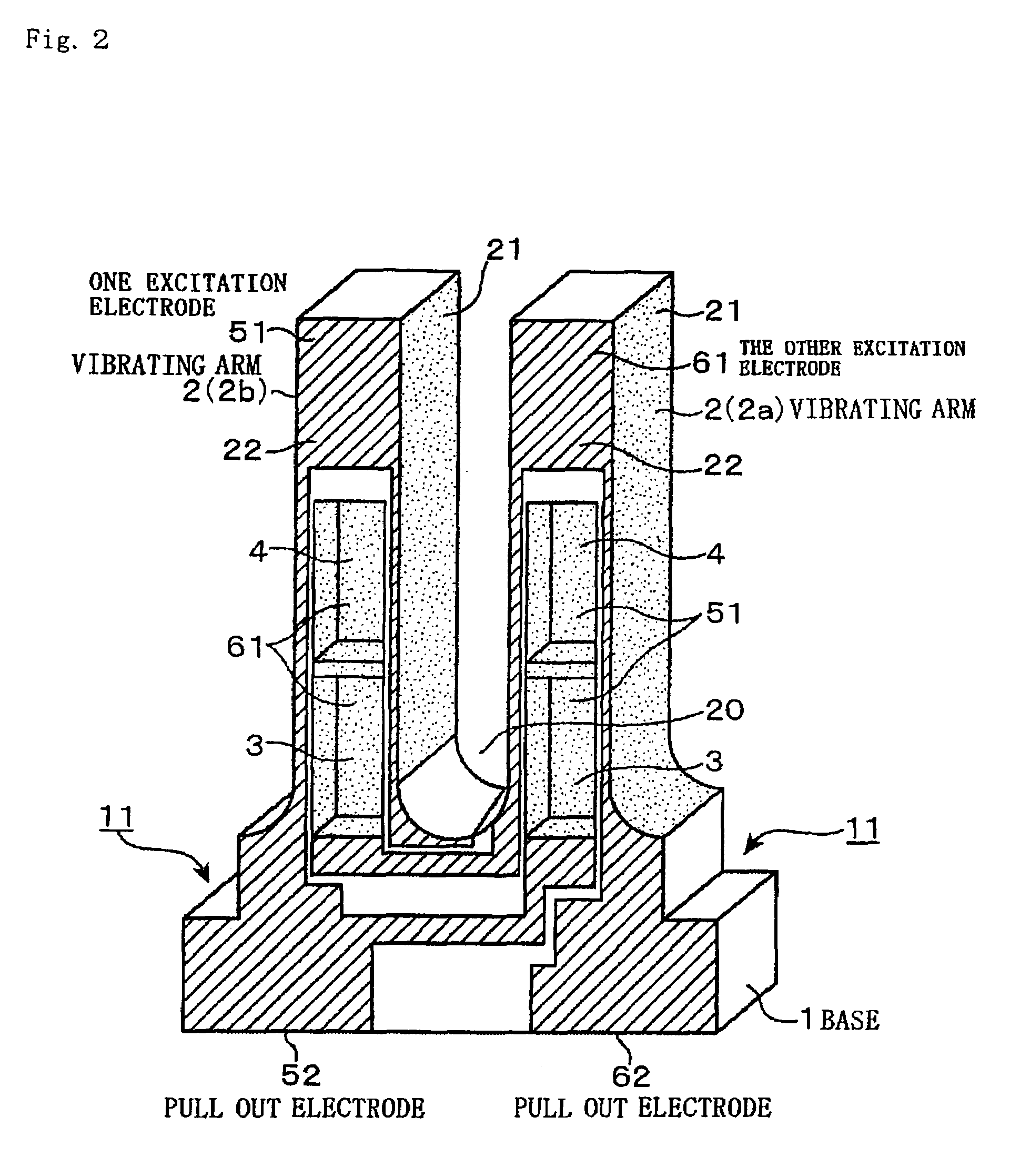
[0024]FIG. 1 is a diagram showing an embodiment of a tuning fork type quartz vibrator relating to the present invention. The quartz vibrator main body (a piece of quartz) in this quartz vibrator includes a substantially square base 1 serving also as a notch portion 11 in which an upper portion of both sides thereof is notched in a rectangle, and two vibrating arms 2 (2a and 2b) extend from an upper side of the base 1 in parallel with a space therebetween, and are formed in an entire shape as a tuning fork type quartz piece. Furthermore, a first groove 3 and a second groove 4 formed by dividing into two parts in the longitudinal direction from a base end of the respective vibrating arm 2 (2a and 2b) toward a tip are provided on a front surface and a back surface of the vibrating arms 2 (2a and 2b).

[0025]A shape of the base 1 between the pair of vibrating arms 2a and 2b is curved, and a position in the Y-direction of the base end of the first groove 3 is at a same position as that of ...

experimental example

Experiment 1

[0033]In a tuning fork type quartz vibrator described in a previously described embodiment, a ratio L2 / L1 of the length L2 of the first groove 3 to the length L1 from the base of the first groove 3 to the tip of the second groove 4 was changed variously, and the strength of respective quartz vibrators was checked. The L2 / L1 is set in the following 5 ways: 0%, 12.5%, 35%, 50% and 65%, expressed by a percentage % ((L2 / L1)×100). 0% means forming one continuous groove without dividing it.

[0034]Other conditions are as follows. The length L0 of the vibrating arms 2 (2a and 2b) is 1650 μm, the L1 from the base of the first groove 3 to the tip of the second groove 4 is 847 μm, the space d of the first groove 3 and the second groove 4 is 10 μm, the length L3 from the bottom surface of the base 1 to the lowest portion 20 of the fork portion of the tuning fork is 600 μm, the width W1 of the vibrating arms 2 (2a and 2b) is 100 μm, the width W2 of the groove 3 is 65 μm, and the width...

experiment 2

[0038]Next, an experiment to find an appropriate value of a space d between the first groove 3 and the second groove 4 was carried out. In this experiment, L2 / L1 was set to be 35% (0.35), and the space d between the first groove 3 and the second groove 4 was changed variously by changing the position on the base end side of the second groove 4 to set d / L1 in 5 ways: 0%, 0.6%, 1.0%, 1.2%, and 2.5l %. Other conditions are the same as in Experiment 1. Strength of each quartz vibrator was examined in the same way as in Example 1. The result is as shown in Table 2 and FIG. 7. Note that the time of d / L1 being 1.2% corresponds to the time of d in the previous Experiment 1 being 10 μm.

[0039]

TABLE 2L2 / L1First TimeSecond TimeThird TimeAverage(%)(g)(g)(g)(g)07.38.86.07.40.68.59.26.98.21.07.810.38.99.01.210.99.68.09.52.524192021

[0040]From this result, it can be said that the wider the space d between both grooves 3 and 4, in other words, the greater the d / L1, the greater the strength of the qua...


PUM


Abstract

A tuning fork type piezoelectric vibrator is provided with vibrating arms which can improve shock resistance while suppressing a CI value to a small value. A first groove (base end side) and a second groove (tip side) extend along a longitudinal direction from a base end of the vibrating arm and are formed on at least one of a front surface or a back surface of the vibrating arms. Then, a ratio L2 / L1 which is the ratio of a length L2 of the first groove to a length L1 from the base end of the vibrating arm to the tip of the second groove, is set between 0.35 and 0.65, and a ratio d / L1 which is the ratio of a space d between the first groove and the second groove to the length L1 from the base end of the vibrating arm to the tip of the second groove, is set between 0.010 and 0.016.

Description

TECHNICAL FIELD[0001]The present invention relates to a piezoelectric vibrator in which two vibrating arms are extended from a base to form in a tuning fork type vibrator.BACKGROUND ART[0002]The piezoelectric vibrator of this kind, such as a tuning fork type quartz vibrator is generally known as a signal source ticking a clock rate of a wrist watch, and has been adopted as a synchronizing signal source of portable electronic devices in recent years. Further miniaturization of quartz vibrators is required with miniaturization of such electronic devices.[0003]The configuration of a tuning fork type quartz vibrator is described in Patent Document 1. In the configuration of the tuning fork type quartz vibrator shown in FIG. 9, tuning fork arms 2a and 2b serving as a pair of vibrating arms are provided on a base 1, and grooves 3 are provided on both main surfaces of the respective turning fork arms 2a and 2b. Excitation electrodes to excite tuning fork vibration based on winding vibratio...

Claims


Application Information

Patent Timeline
Patent Type & Authority Patents(United States)
IPC IPC(8): H03H9/21
CPCH03H9/215D04B33/00D04B27/08D04B35/02D04B37/06
Inventor KAWANISHI, SHINGOISHIHARA, MINORUONO, KOZO
Owner NIHON DEMPA KOGYO CO LTD
Why Eureka
Try Eureka