
Phase-locked loop bandwidth calibration circuit and method thereof

a phase-locked loop and bandwidth calibration technology, which is applied in the direction of digital transmission, continuous tuning, modulation, etc., can solve the problems of limiting the purity of the output signal, the uncertainty of the output frequency to the applied input voltage, and the undesirable phase noise at the voltage-controlled oscillator outpu

Inactive Publication Date: 2008-04-01
MEDIATEK INC
View PDF8 Cites 70 Cited by
  • Summary
  • Abstract
  • Description
  • Claims
  • Application Information

AI Technical Summary

Benefits of technology

The present invention provides a phase-locked loop bandwidth calibration circuit, a phase-locked loop circuit, a method of calibrating a phase-locked loop bandwidth, and a system for processing received radio-frequency signals. The technical effects of the invention include improved phase-locked loop bandwidth calibration, improved phase-locked loop circuit performance, and improved system performance for processing received radio-frequency signals.

Problems solved by technology

A typical drawback of a voltage-controlled oscillator is its uncertainty in output frequency to the applied input voltage due to integrated circuit process variations.
This phase noise at the voltage-controlled oscillator output is undesirable as this limits the purity of the output signal.
For signal reception, impure frequency sources result in mixing of undesired channels into the desired channel signal.
For signal transmission, impure frequency sources create interference in neighboring channels and limit a receivers ability to recover the transmitted data.
The level of spectral purity required in cellular telephone applications makes the design of a phase-locked loop frequency synthesizer solution quite demanding.
Phase noise is undesired energy spread continuously in the vicinity of the output frequency.
Phase noise can be the most damaging of the three to the spectral purity of the output frequency.
In general, a wider bandwidth will lead to faster settling but will result in higher noise.
In turn, the varying of the phase-locked loop bandwidth causes less control in phase-locked loop settling time and in phase-locked loop noise.

Method used


Image

  • Phase-locked loop bandwidth calibration circuit and method thereof
  • Phase-locked loop bandwidth calibration circuit and method thereof
  • Phase-locked loop bandwidth calibration circuit and method thereof

Examples


Embodiment Construction

[0040]As noted above, the present invention contemplates a method and apparatus for synthesizing high-frequency signals by implementing a phase-locked loop frequency synthesizer with a voltage controlled oscillator.

[0041]A more detail description of such a method and apparatus for synthesizing high-frequency signals by implementing a phase-locked loop frequency synthesizer with a voltage controlled oscillator is set forth in co-pending patent application Ser. No. 10 / 230,763, filed on Aug. 29, 2002, entitled “Method Of Modulation Gain Calibration And System Thereof.” The entire content of co-pending patent application, Ser. No. 10 / 230,763, filed on Aug. 29, 2002, is hereby incorporated by reference.

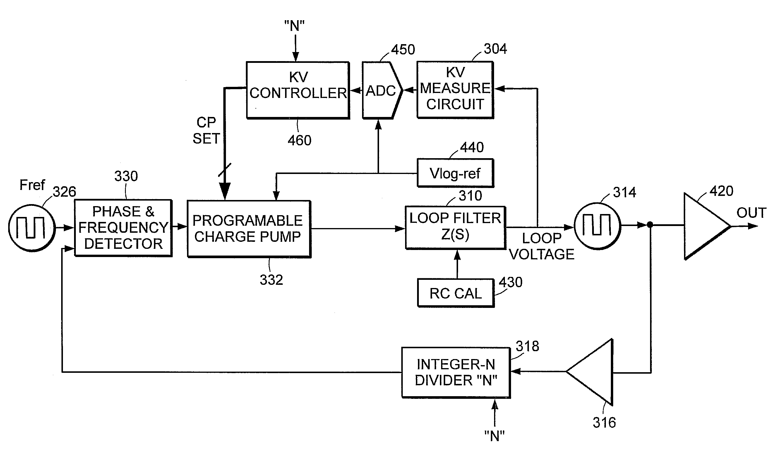
[0042]FIG. 3 illustrates an example of an apparatus for synthesizing high-frequency signals by implementing a phase-locked loop frequency synthesizer with a voltage-controlled oscillator.

[0043]As shown in FIG. 3, a sigma-delta modulator and digital to analog converter circuit 300 receives ...


PUM


Abstract

A phase-locked loop frequency synthesizer has a charge pump, phase-locked loop filter, voltage-controlled oscillator, and a bandwidth calibration circuit. The bandwidth calibration circuit measures the gain of the voltage-controlled oscillator and uses the measured voltage-controlled oscillator gain to adjust the charge pump level. The charge pump level is adjusted so that a product of the voltage-controlled oscillator gain and the measured charge pump level results in a constant phase-locked loop bandwidth.

Description

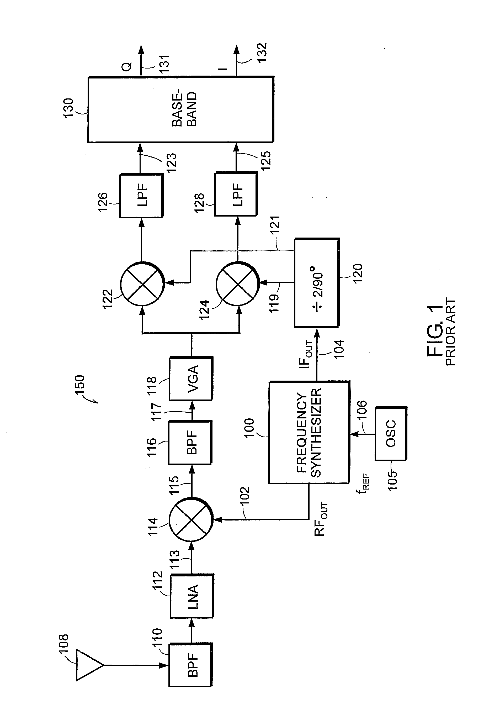
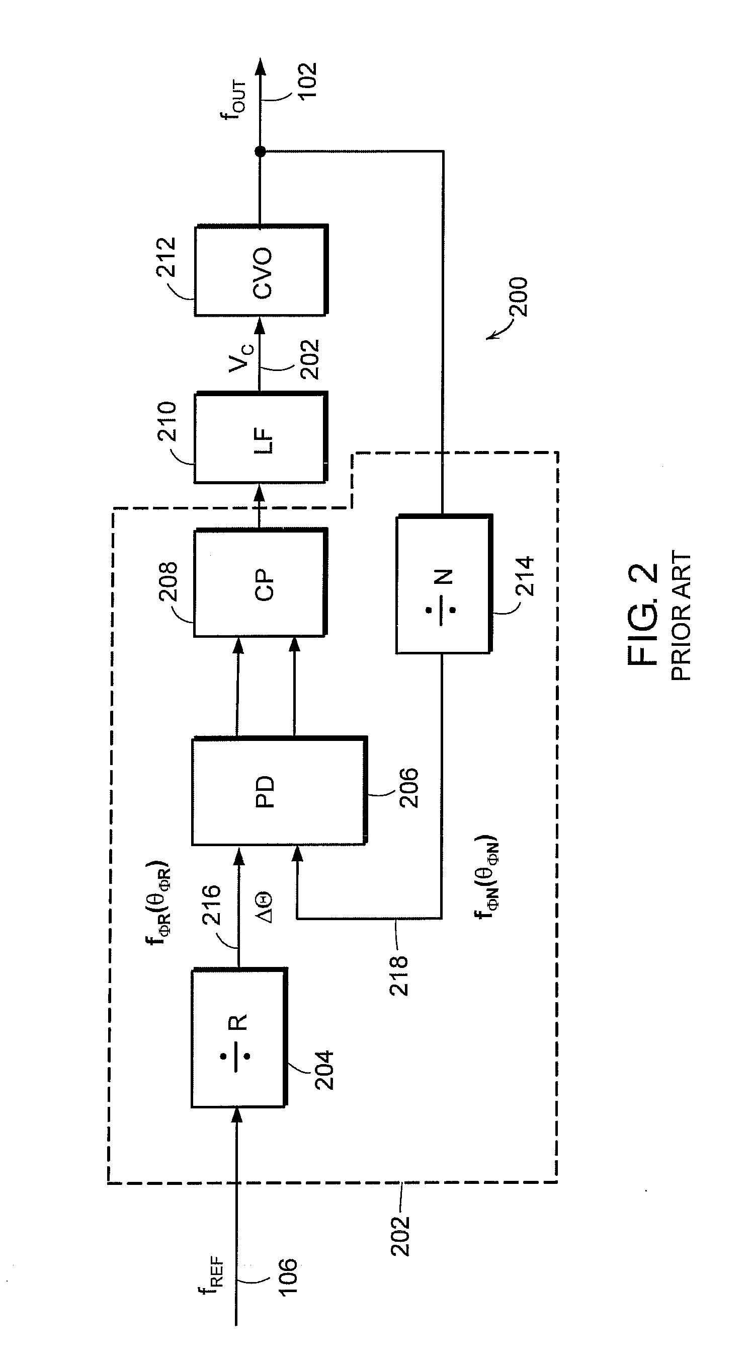
FIELD OF THE PRESENT INVENTION[0001]The present invention is directed to a frequency synthesizer having a phase-locked loop and voltage-controlled oscillator. More particularly, the present invention is directed to a frequency synthesizer having a phase-locked loop bandwidth calibration circuit that establishes a phase-locked loop bandwidth quickly based upon an external frequency reference.BACKGROUND OF THE PRESENT INVENTION[0002]Phase-locked loops are used in a variety of applications such as clock recovery, frequency and phase modulation, and frequency synthesizers. A voltage-controlled oscillator is a central design element of the phase-locked loop, whereby the voltage-controlled oscillator produces an output frequency proportional to its input voltage.[0003]A typical drawback of a voltage-controlled oscillator is its uncertainty in output frequency to the applied input voltage due to integrated circuit process variations. This leads to the need for a voltage-controlled oscillat...

Claims


Application Information

Patent Timeline
Patent Type & Authority Patents(United States)
IPC IPC(8): H03L7/085H03C3/09H03J3/00H03L7/089H03L7/093H03L7/197H04L27/00
CPCH03C3/0925H03C3/0933H03C3/0941H03C3/095H03J3/00H03L7/0805H03L7/0898H03L7/093H03L7/1976H03L7/0893H04L2027/0081
Inventor BALBONI, EDMUND J.PALMER, WYN T.STRANGE, JONATHAN R.
Owner MEDIATEK INC
Learn More