Packet switching fabric having a segmented ring with token based resource control protocol and output queuing control

a packet switching fabric and resource control technology, applied in data switching networks, bus networks, digital transmission, etc., can solve the problems of reducing reducing the maximum number of cards which may be added, and achieving scalability of the number of network ports, so as to reduce the delay of packet transfer operations and accelerate the effect of switching operations

Inactive Publication Date: 2008-04-01
AVAGO TECH INT SALES PTE LTD
View PDF16 Cites 36 Cited by
  • Summary
  • Abstract
  • Description
  • Claims
  • Application Information

AI Technical Summary

Benefits of technology

[0028]An important advantage of the packet switching fabric of the present invention is that it provides reduced delays in packet transfer operations, and therefore faster switching operations.

Problems solved by technology

One problem with cross bar switching devices is achieving scalability of the number of network ports.
Because of the N×N complexity of the interconnection resources, exponential costs are incurred when increasing the number of network ports of a cross bar switching device.
One problem with such switching devices is modularity.
While a number of cards having additional network ports may be inserted into slots of the back plane to increase the total number of network ports, the maximum number of cards which may be added is limited because the back plane may support only a limited number of cards due to loading effects on the back plane.
Therefore, the modularity problem of bus architecture packet switching fabrics imposes a limit on the scalability of the number of network ports of the fabric.
Therefore, prior art ring architecture switching fabrics are not commonly used for network switching which requires high data throughput.
However, this is undesirable because the use of large buffers limits the number of network ports which can be implemented on an integrated circuit chip.

Method used


Image

  • Packet switching fabric having a segmented ring with token based resource control protocol and output queuing control
  • Packet switching fabric having a segmented ring with token based resource control protocol and output queuing control
  • Packet switching fabric having a segmented ring with token based resource control protocol and output queuing control

Examples


Embodiment Construction

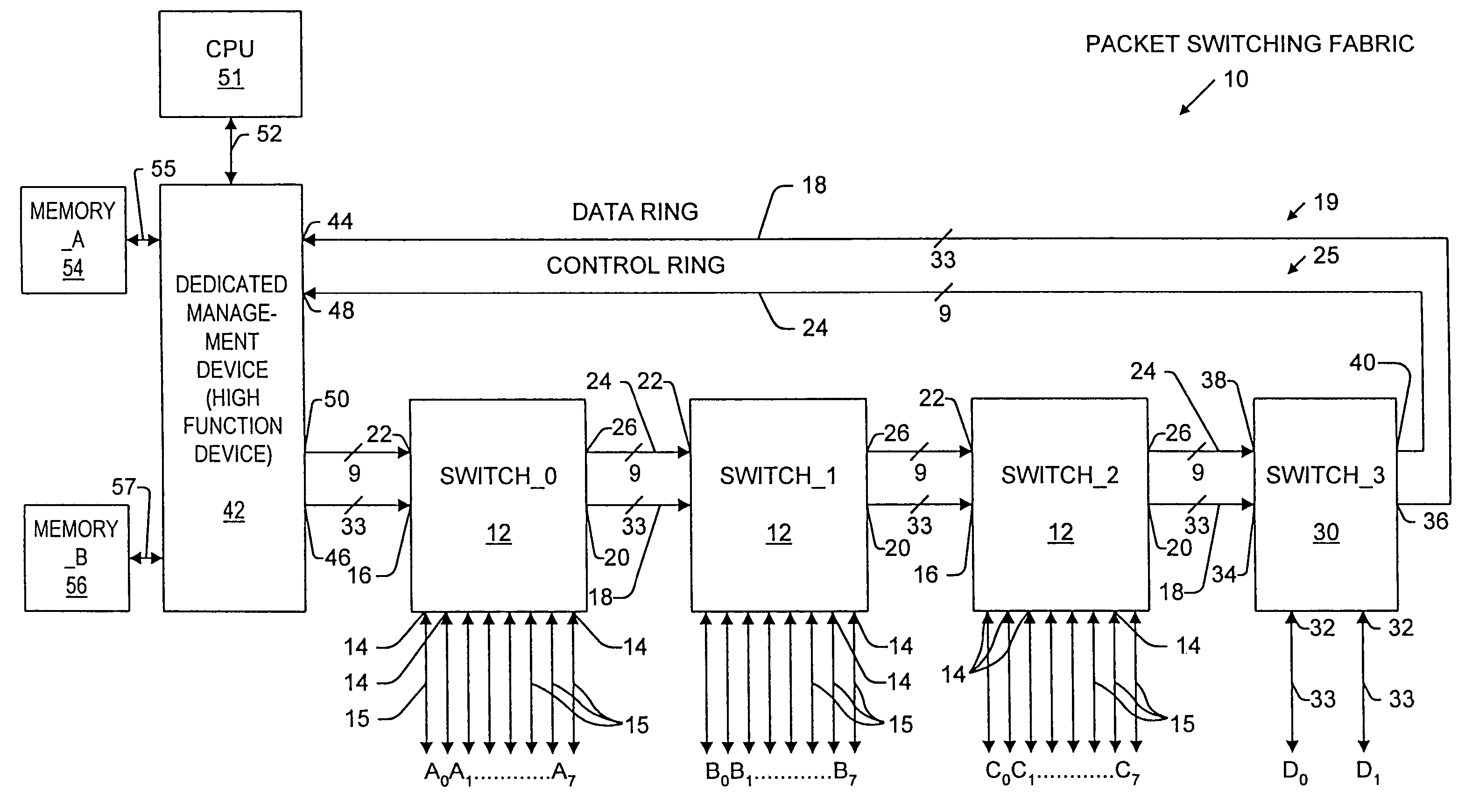
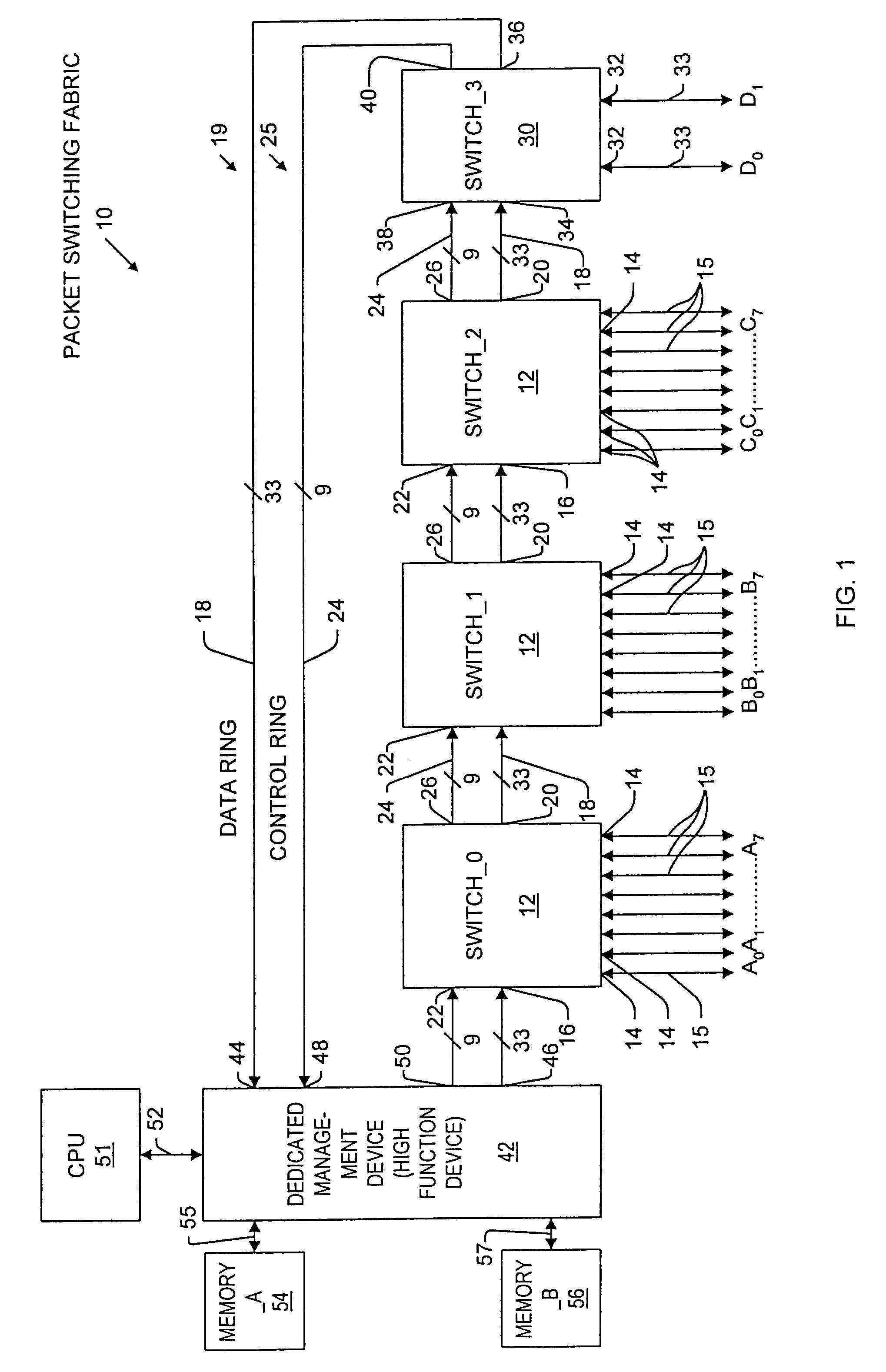
[0046]FIG. 1 shows a schematic block diagram of a packet switching fabric at 10 according to the present invention, the fabric 10 including three cut-through packet transfer switching devices 12, designated SWITCH_0, SWITCH_1, and SWITCH_2, each having: eight network ports 14 designated (A0, A1, . . . , A7), (B0, B1, . . . , B7), and (C0, C1, . . . , C7) respectively for transmitting and receiving data packets via corresponding lower and middle bandwidth ETHERNET links 15 each having a bandwidth of either 10 Mbps or 100 Mbps; a data ring input port 16 for receiving data and data ring messages from an upstream device via a corresponding one of a plurality of 33-bit data ring segments 18; a data ring output port 20 connected to transmit data and data ring messages to a corresponding downstream device via a corresponding one of the data ring segments 18; a control ring input port 22 for receiving control messages, which include output queuing controlled packet transfer protocol message...


PUM


Abstract

A packet switching fabric includes means forming a data ring, means forming a control ring, and means forming a plurality of data communication network links each having at least one network node coupled thereto. The fabric further includes a plurality of output queuing controlled switching devices coupled together by the data ring means and the control ring means so that the network links can be selectively communicatively coupled. Each of the output queuing controlled switching devices includes control ring processing means operative to develop, transmit and receive control messages to and from adjacent ones of the devices via the control ring means. The control messages provide for controlling packet transfer operations including transmitting associated selected ones of the received data packets from the associated source device to the associated destination device via an associated source-destination channel path including associated ones of the data ring segments and an associated one of the memory unit links. A channel resource patrol message is passed by each one of the devices, the patrol message carrying channel bandwidth information indicative of bandwidth available on the data ring means and bandwidth available on memory unit links. The control ring processing means is responsive to the channel bandwidth information and operative to read and modify the channel bandwidth information for the purpose of managing data transfer via the data ring means and via each of the memory unit links.

Description

CROSS-REFERENCE TO RELATED APPLICATIONS[0001]Reference is made to and priority claimed from U.S. Provisional Application Ser. No. 60 / 123,091, filed Mar. 5, 1999, entitled “Packet Switching System.”BACKGROUND OF THE INVENTION[0002]The present invention relates generally to packet switching fabrics for use in data communications networks. Specifically, the present invention pertains to a packet switching fabric having a plurality of switching devices arranged in a ring topology and operating in accordance with an output queuing controlled packet transfer protocol.DESCRIPTION OF THE PRIOR ART[0003]Switching devices are essential components of data communication networks including local area networks (LANs), such as ETHERNET, and wide area networks (WANs). Common switching devices include cross bar switching devices, and packet switching fabrics. A packet switching fabric is an interconnection architecture which uses multiple stages of switches to route transactions between a source add...

Claims


Application Information

Patent Timeline
Patent Type & Authority Patents(United States)
IPC IPC(8): H04L12/56H04L12/40H04L12/42H04L12/44
CPCH04L12/42H04L12/44H04L49/102H04L49/201H04L49/254H04L49/3018H04L49/3027H04L2012/445
Inventor DAI, WILLIAMCHAO, JASONLIU, YAO-CHING
Owner AVAGO TECH INT SALES PTE LTD
Why Eureka
Try Eureka