Motor-driven reinforcing rod binding machine

a technology of reinforcing rods and binders, which is applied in the direction of bundling machine details, barbed wires, applications, etc., can solve the problems of insufficient motor cooling effect, large load on the operation of twisting the binding wire, and large heat generated by the motor in charge of twisting operation, etc., and achieve the effect of continuous running of the reinforcing bar binder

Active Publication Date: 2008-04-08
MAX CO LTD
View PDF18 Cites 9 Cited by
  • Summary
  • Abstract
  • Description
  • Claims
  • Application Information

AI Technical Summary

Benefits of technology

[0007]In view of the above circumstance, an object of the invention is to provide a cooling device which can control the temperature of a reinforcing bar binder within an appropriate range to permit its long-time continuous operation and extremely suppress power consumption due to cooling.

Problems solved by technology

However, in either type, the operation of twisting the binding wire is subjected to considerable load and the motor in charge of the twisting operation generates a large quantity of heat.
However, in the reinforcing bar binder, in which the operation pattern of the motor is different from that of the electric tool such as an electric drill or an electric driver, a sufficient motor cooling effect cannot be obtained by the fan which rotates simultaneously with the motor.
Therefore, the reinforcing bar binders have not been specially provided with cooling means such as fans.
Therefore, even with the fan attached to the motor shaft, the rotation time within the one cycle is short.
Thus, a satisfactory cooling effect cannot be expected.
In this case, the reinforcing bar binder cannot be employed until the interior temperature falls to a safety reference value.
In a large-scale construction scene such as bridge or road construction, although the reinforcing bar binder is continuously driven all day long, it cannot be employed owing to temperature rise so that working must be interrupted.
This may leads to delay in a work schedule.
For example, if the reinforcing bar binder is simply provided with an electric fan connected to a power switch, the electric fan which always rotates consumes a large quantity of electric power.
This leads to an inconvenience of shortening the duration of a battery of the reinforcing bar binder.
Further, in a very low temperature environment in which the atmospheric temperature is not higher than 0° C., the viscosity of lubricant applied to a rotating mechanism portion of the reinforcing bar binder lowers to increase the operation resistance and reduce the battery capacity.
This leads to a problem that the interior of the reinforcing bar binder is cooled to the temperature not higher than a suitable operation temperature to deteriorate the performance.

Method used


Image

  • Motor-driven reinforcing rod binding machine
  • Motor-driven reinforcing rod binding machine
  • Motor-driven reinforcing rod binding machine

Examples


first embodiment

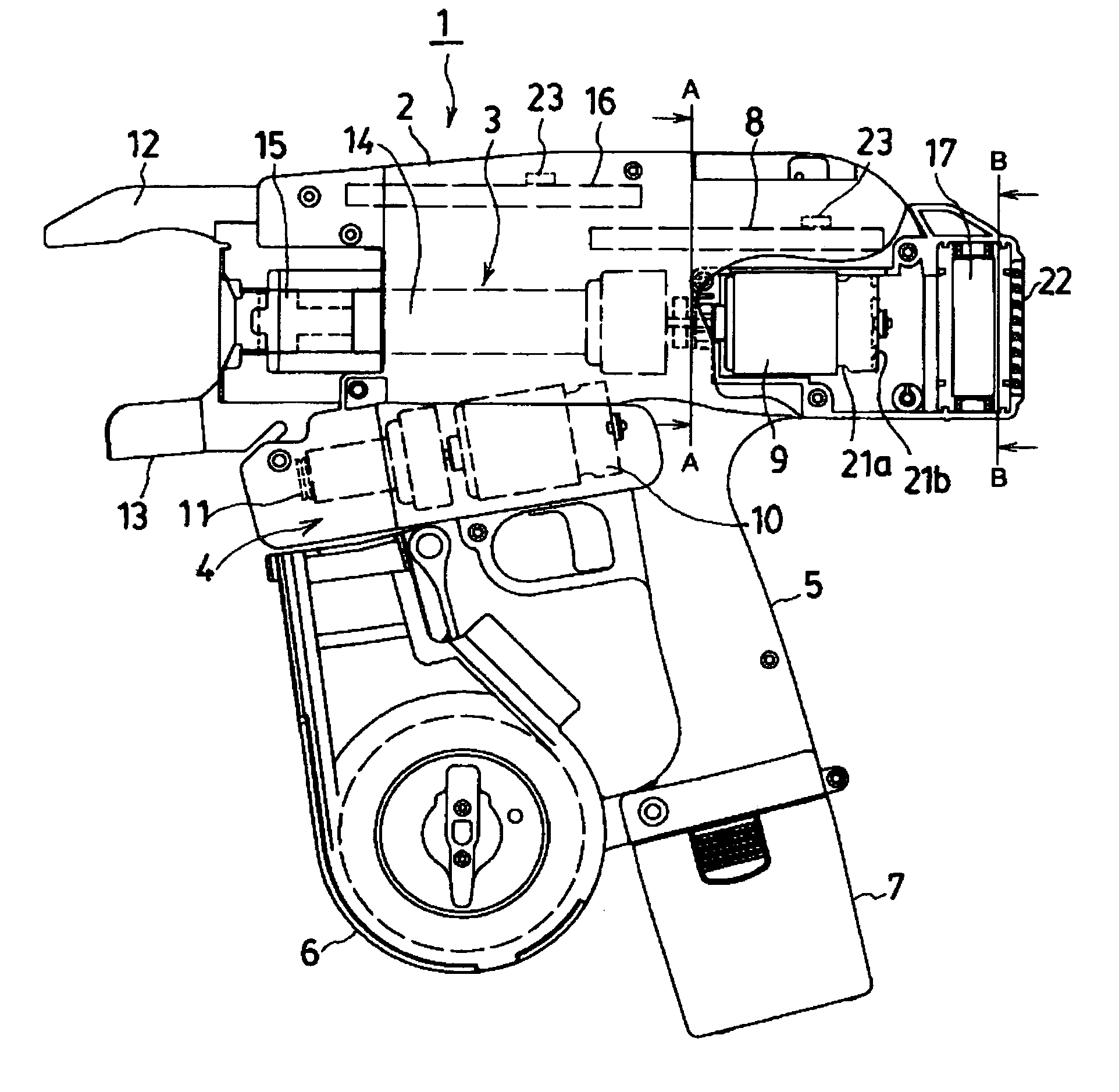
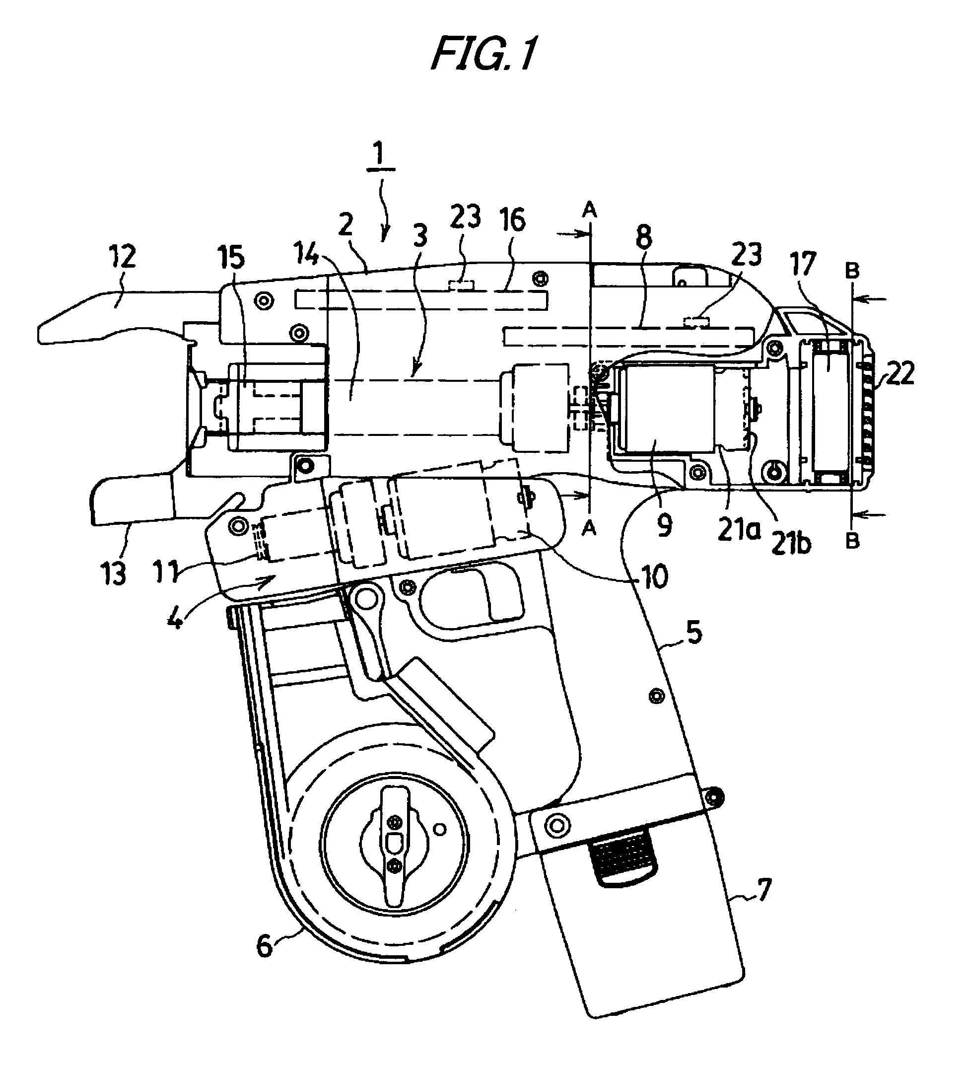
[0020]FIG. 1 shows a reinforcing bar binder 1. A housing 2 incorporates a binding wire twisting mechanism 3 and a binding wire feeding mechanism 4. Within a magazine 6 arranged in front of a grip 5 of the housing 2, a binding wire reel (not shown) is loaded. On the end of the grip 5, a battery 7 is loaded to supply, through a power supply circuit board 8 (inclusive of a control circuit), electric power to a twisting motor 9 of the binding wire twisting mechanism 3 and a feeding motor 10 of the binding wire feeding mechanism 4.

[0021]The binding wire feeding mechanism 4 has two V-groove equipped gears 11 in mesh with each other, arranged in a front-rear direction of paper face in FIG. 1. The one V-groove equipped gear is driven by the motor 10, and the binding wire sandwiched by the two V-groove equipped gears 11 is fed. The binding wire wound on the binding wire reel is fed out upwards by the binding wire feeding mechanism 4. The binding wire thus fed out is shaped in an arc along th...

second embodiment

[0027]An example of more precise control than the first embodiment is shown in FIG. 5. When the main switch of the reinforcing bar binder 1 is turned on to turn on the power (step 201), information on the interior temperature of the reinforcing bar binder is sequentially supplied to the comparison control means through the heat sensitive elements. And if the trigger switch for the reinforcing bar binder is operated to input an ON signal (step 202), the interior temperature at this time is compared with a reference temperature (now, for example, 0° C.) (step 203). If the interior temperature is not higher than the reference temperature, without actuating the cooling fan 17, the binding operation is executed (step 204). Upon completion of the one cycle binding operation, the control processing is returned to step 202.

[0028]If the interior temperature exceeds 0° C., the binding operation is executed and the cooling fan 17 is also actuated (step 205). Counting of a predetermined on-dura...


PUM

PropertyMeasurementUnit
temperatureaaaaaaaaaa
interior temperatureaaaaaaaaaa

Abstract

A cooling fan 17 is arranged on the rear side of a twisting motor 9 of a reinforcing bar binder 1. The cooling fan is located on the axial line of the twisting motor so that cooling air effectively flows along the surface of the twisting motor and through within the twisting motor. A control unit on-off controls the cooling fan according to the temperature detected by a heat sensitive element 23 so as to actuate the cooling fan when a trigger signal is received at an interior temperature not lower than a reference value and to stop it after a predetermined time elapses. Thus, the temperature of the reinforcing bar binder can be controlled within a safe temperature range. Even if the reinforcing bar binder is run during a long time, a protecting circuit is not operated to forcibly stop the reinforcing bar binder. Further, in a cold environment, the cooling fan is not actuated so that the performance at a low temperature is not deteriorated and so power consumption can be also saved.

Description

TECHNICAL FIELD[0001]This invention relates to a motor-driven reinforcing bar binder, and more particularly to a cooling device for the reinforcing bar binder having a temperature control function.BACKGROUND ART[0002]There is previously known motor-driven reinforcing bar binders which are provided with a binding wire feeding mechanism for feeding a binding wire being bent in a loop shape to be wound over a reinforcing bar and a binding wire twisting mechanism for twist and binding the binding wire wound around the reinforcing bar, wherein a binding wire feeding operation and a binding wire twisting operation are successively performed by a trigger operation to perform a once-cycle binding operation (see, e.g. JP-U-05-003494 and JP-A-2003-064876). These reinforcing bar binders include a single-motor type in which the binding wire feeding mechanism and the binding wire twisting mechanism are driven by a single motor and a two-motor type in which the binding wire feeding mechanism and ...

Claims


Application Information

Patent Timeline
Patent Type & Authority Patents(United States)
IPC IPC(8): B21F9/02B21F25/00B65B13/28B65B13/18E04G21/12
CPCB65B13/187E04G21/122E04G21/123
Inventor KUSAKARI, ICHIROMATSUOKA, ATSUSHI
Owner MAX CO LTD
Why Eureka
Try Eureka