Direct measurement of Brillouin frequency in distributed optical sensing systems

a technology of optical sensing and direct measurement, applied in the field of sensing systems, can solve the problems of inability to determine, slow sweep process, and limited rate, so as to reduce noise, improve accuracy, and improve accuracy

Inactive Publication Date: 2008-04-08
SENSORNET
View PDF4 Cites 77 Cited by
  • Summary
  • Abstract
  • Description
  • Claims
  • Application Information

AI Technical Summary

Benefits of technology

[0011]By using such a converter, there is no longer a need for time consuming spectrum analysis to obtain the Brillouin frequency. Avoiding such spectrum analysis avoids the time consuming scanning of frequencies to obtain the spectrum, and avoids the heavy processing load of deducing a peak or average frequency from the spectrum. In some cases this can improve measurement rates by factors of 10s or even 100s. Consequences of such faster measurement include enabling more samples to be included in averaging. As sensing accuracy typically varies according to a square root of the number of samples being averaged, this can give a significant increase in accuracy. More rapid changes in the conditions being sensed can be detected. Useful information can be derived from a spectrum of frequencies of changes in strain, and the faster measurement can enable a wider spectrum to be measured, into the domain of acoustic analysis. The faster measurement can be traded for other advantages such as greater reach, or greater spatial resolution, for a given level of noise. The Brillouin frequency can be used to sense strain for example, or to correct sensing of other conditions such as temperature. It can be combined with other techniques to increase the flexibility of the sensing, to give fine sensing over a small range or coarse sensing over a wide range for example. In principle, these advantages can apply regardless of whether the converter is implemented in the optical domain or electrical domain. Similarly, in principle, the advantages can apply whether the Brillouin component is distinguished from other components of the scattered light, before or after the converter. They can apply to a system which sends pulses or a continuous illumination.
[0037]This is a particularly effective way of achieving such distributed measurements. It can be easier to implement and more rugged than alternatives such as discrete point sensors such as micro benders fitted along the waveguide. There is no need to predetermine the location of sensors. The distributed nature can give more information than point sensors, enabling tracking of anomalies as they propagate along a pipe for example, or precise detection of leaks for example.

Problems solved by technology

The sweeping process can take some time especially since the signal under study is extremely noisy in nature.
This rate is usually limited by the fact that it is normally only possible to usefully have one pulse in the fibre at any time as otherwise it would not be possible to determine where the returning signal was generated (the backscattered signals from the multiple pulses would overlap).
A disadvantage of this is the time required to change the optical source wavelength between different positions.
This in turn can introduce frequency errors depending on the accuracy and repeatability of the optical source wavelength tuning.
Once again this method requires frequency sweeping of a source, this time an RF oscillator, which reduces the achievable measurement speed.

Method used


Image

  • Direct measurement of Brillouin frequency in distributed optical sensing systems
  • Direct measurement of Brillouin frequency in distributed optical sensing systems
  • Direct measurement of Brillouin frequency in distributed optical sensing systems

Examples


Embodiment Construction

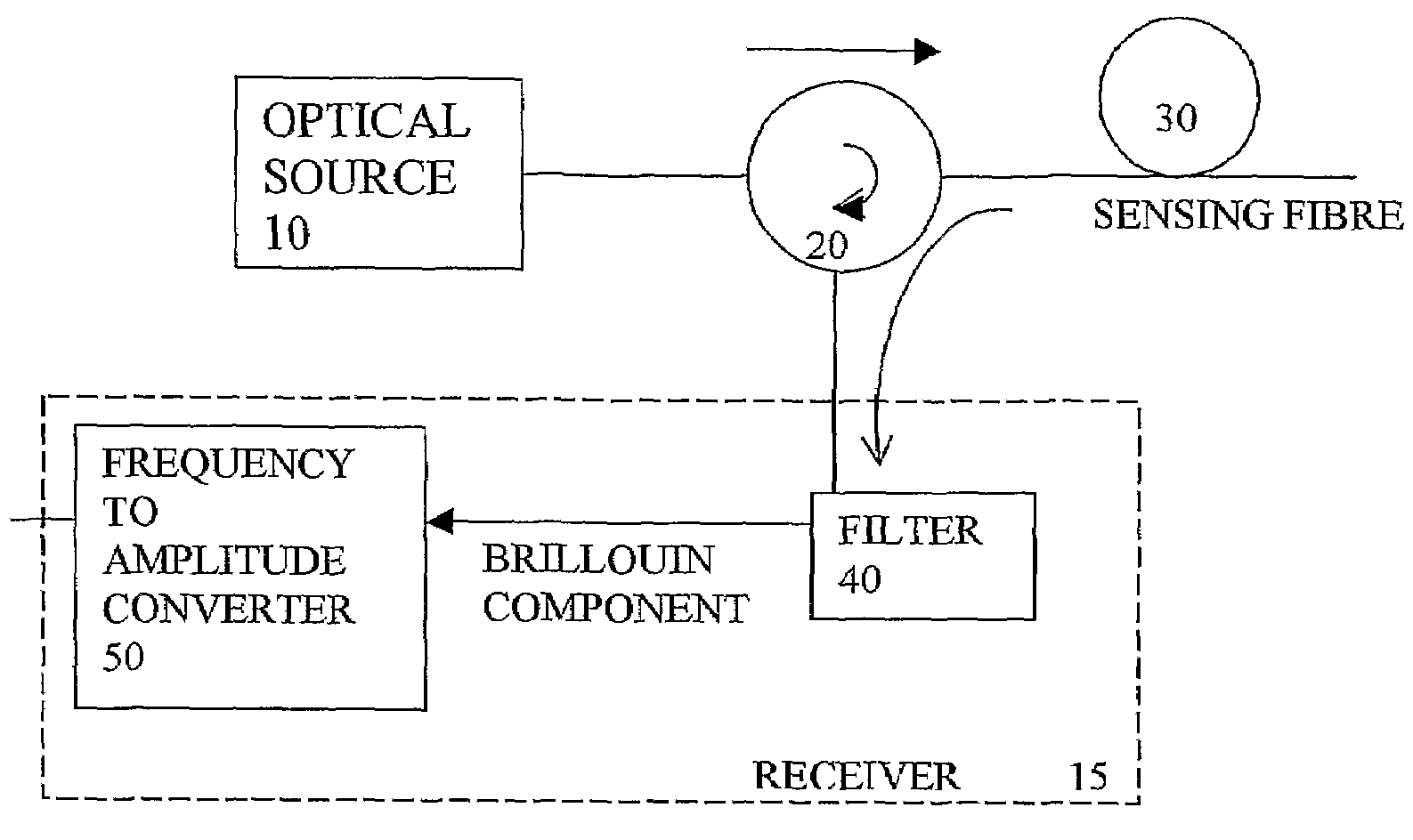
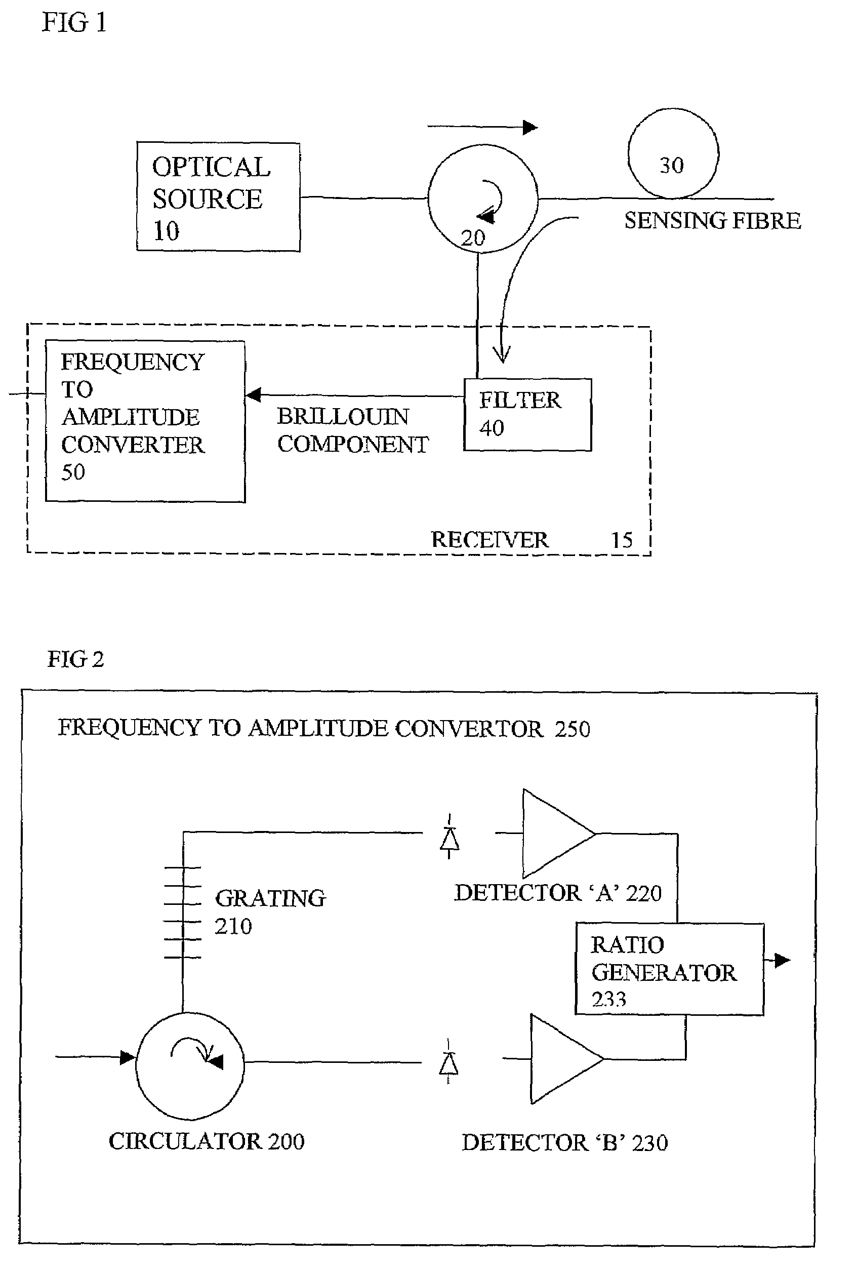
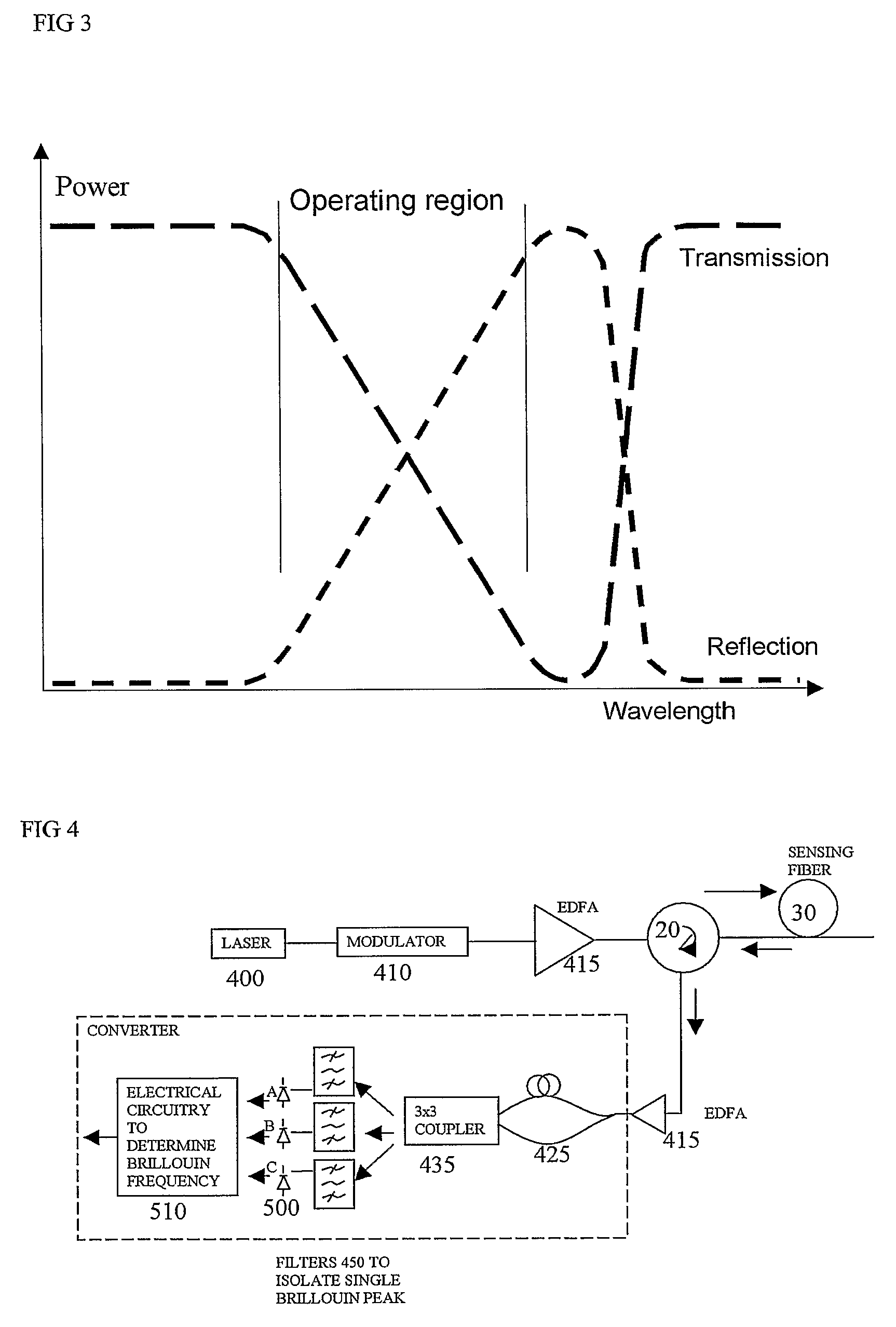
[0054]The embodiments described use an optical or electrical arrangement, with static characteristics, to directly translate the Brillouin backscatter spectrum into measures of frequency and power, from which temperature and strain can be calculated. One significant difference is dispensing with the need to acquire a detailed picture of the Brillouin spectrum. This can provide a significant increase in measurement speed since the Brillouin spectrum no longer needs to be captured through the frequency sweeping of an optical or electrical element. This technique can be coupled with the optical time domain reflectometry technique of launching a single pulse and time resolving the backscatter to provide fully distributed measures of temperature and strain in a fibre.

[0055]The use of a reference section of fibre, as has been described in earlier Sensornet U.S. Pat. No. 6,380534, is one way of allowing this technique to be self calibrating, and provide simultaneous measures of both power ...


PUM

PropertyMeasurementUnit
path lengthaaaaaaaaaa
frequency shiftaaaaaaaaaa
frequencyaaaaaaaaaa

Abstract

An optical sensing system uses light scattered from a sensing fibre to sense conditions along the fibre, and has a receiver with a frequency to amplitude converter to obtain a frequency of a Brillouin component of the received scattered light, to deduce the conditions. This converter can avoid time consuming scanning of frequencies to obtain the Brillouin frequency spectrum, and avoids the heavy processing load of deducing a peak or average frequency from the spectrum. The converter can be implemented in the optical domain using a grating or interferometer, or in the electrical domain using a diplexer or electrical interferometer. It can generate complementary signals, having opposite signs, a ratio of these signals representing the frequency. This can avoid sensitivity to amplitude changes in the received scattered signals and provide common mode rejection of noise.

Description

FIELD OF THE INVENTION[0001]The present invention relates to sensing systems, to receivers for such systems, to corresponding methods of sensing, methods of producing sensing signals, methods of making sensing systems and software for such methods.BACKGROUND[0002]There is a requirement in industry for the measurement of conditions such as strain or temperature at all points over long distances. Typical uses are for monitoring oil and gas wells, long cables and pipelines. Distributed temperature sensors often use Raman or Brillouin components of scattered light in optical fibres as the means to determine the temperature. Here, light from an optical source is launched into a fibre and the small amount of light that is scattered back towards the source is analysed. By using pulsed light and measuring the returning signal as a function of time, the backscattered light can be correlated to distance along the fibre. This backscattered light contains a component which is elastically scatte...

Claims


Application Information

Patent Timeline
Patent Type & Authority Patents(United States)
IPC IPC(8): G01J1/04G01J1/42G01J5/08E21B47/10G01D5/353G01K11/32G01M5/00G01M11/08
CPCE21B47/102G01K11/32G01M5/0025G01D5/35364G01M5/0091G01M11/083G01M5/0041E21B47/113E21B47/114
Inventor WATLEY, DANIEL ANDREWFARHADIROUSHAN, MAHMOUDSHAW, BARRY JOHN
Owner SENSORNET
Why Eureka
Try Eureka