
Methods and apparatus for optimizing combined cycle/combined process facilities

a technology of combined cycle and process plant, applied in the direction of total factory control, programme control, instruments, etc., can solve the problems of not necessarily causing the largest impact on the economical generation of electricity and water, not necessarily facilitating the maximizing of reducing the efficiency of the combined system. , to achieve the effect of facilitating enhancing the efficiency of the combined cycle electrical generating/steam-utilizing process plant and enhancing the efficiency of the combined cycl

Inactive Publication Date: 2008-04-08
GENERAL ELECTRIC CO
View PDF15 Cites 65 Cited by
  • Summary
  • Abstract
  • Description
  • Claims
  • Application Information

AI Technical Summary

Benefits of technology

This approach optimizes the efficiency and economic performance of combined cycle power and process plants by determining optimal settings for gas turbines, desalination plants, and other parameters, ensuring cost-effective and reliable operation.

Problems solved by technology

However, designing combination plants may be difficult, as each plant may have operating characteristics that are different than every other plant in the combined cycle / combined process plant system, such that an operating efficiency of each plant, defined in terms of the utilization of resources per unit of output, may be different than the operating efficiency of every other plant.
For example, within a combined electric generating plant and water desalination process plant, although several resources may be used to generate electricity and / or to desalinate water, improving the efficiency of each plant's use of resources may not necessarily cause the largest impact to the economical generation of electricity and production of water.
However, maximizing the efficiency of each individual plant may not facilitate maximizing the efficiency of the combined system.
However, because the conditions that influence each plant's efficiency and the efficiency of the combined production facility constantly change, it may be difficult to monitor and properly adjust plant parameters to achieve an optimum efficiency for the combined production facility.

Method used


Image

  • Methods and apparatus for optimizing combined cycle/combined process facilities
  • Methods and apparatus for optimizing combined cycle/combined process facilities
  • Methods and apparatus for optimizing combined cycle/combined process facilities

Examples


Embodiment Construction

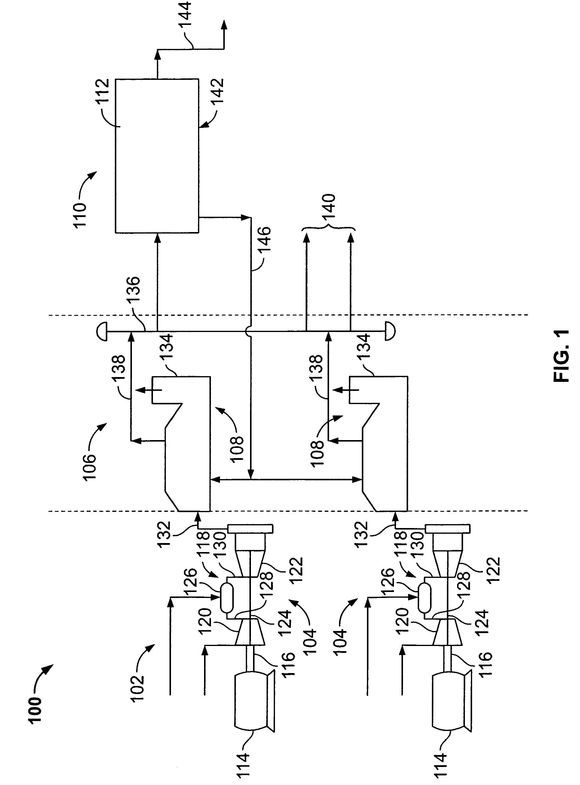
[0014]FIG. 1 is a schematic illustration of an exemplary combined cycle / combined process plant 100. In the exemplary embodiment, plant 100 includes an electrical generation portion 102 that includes a pair of gas turbine power plants 104, a heat recovery portion 106 that includes a pair of heat recovery steam generators (HRSG) 108, and a process plant portion 110 that includes a desalination plant 112. Generation portion 102 may be configured using a combination of thermal power electrical generating plants that may include, but is not limited to, gas turbine engines, fossil-fired boilers, biomass-fired boilers, waste recovery boilers, waste incinerating furnaces, nuclear boilers, geothermal sources, and solar sources. Heat recovery portion 106 may be configured with non-fired and fired heat recovery steam generators, as well as other known heat recovery devices. Process plant portion 110 may include various types of plants that use heat as an input to the process, including, but no...


PUM


Abstract

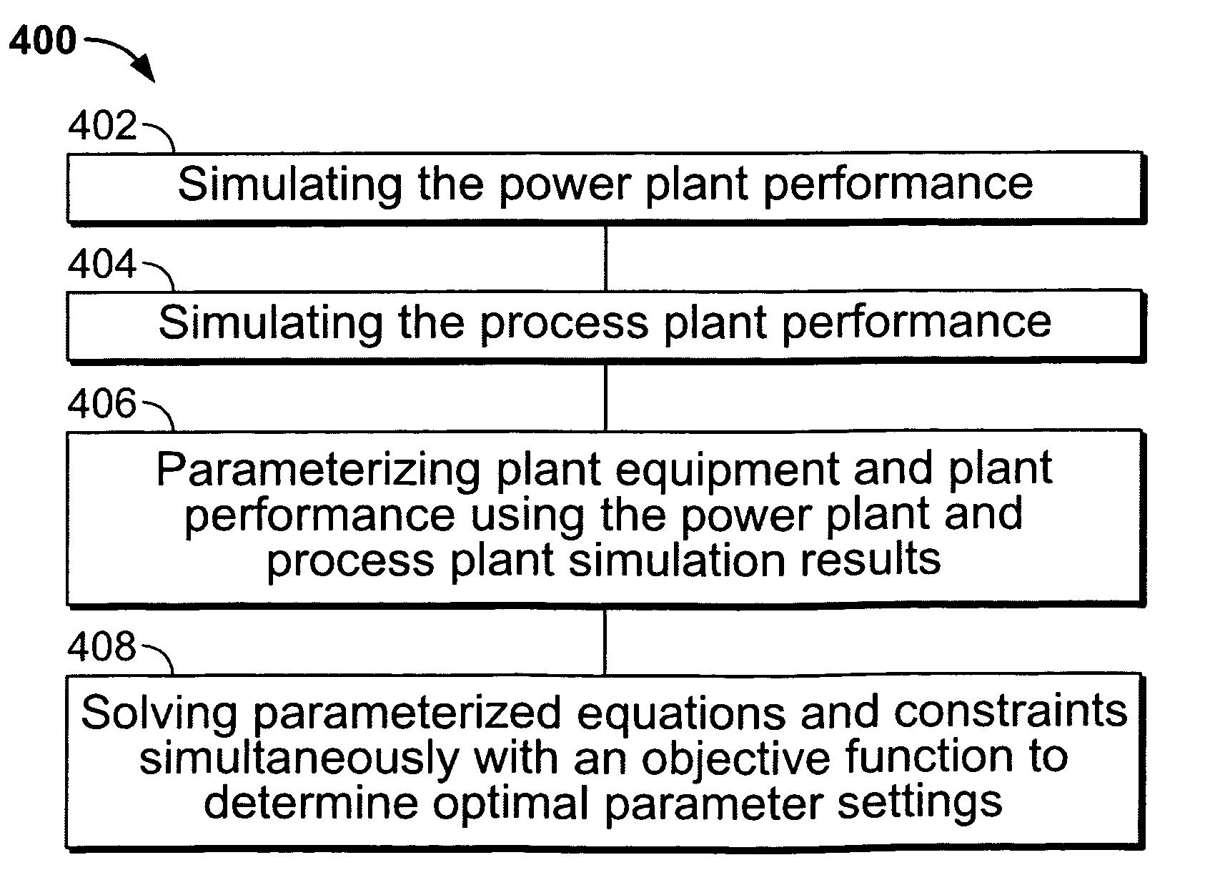
Methods and systems for operating combined cycle electrical generating plants is provided. The method includes simulating the electrical power plant performance, simulating the steam utilizing process plant performance, parameterizing plant equipment and plant performance using the power plant and process plant simulation results, and solving parameterized simultaneous equations and constraints with an objective function to determine parameter settings that facilitate enhancing an efficiency of the combined cycle electrical generating / steam-utilizing process plant.

Description

BACKGROUND OF THE INVENTION[0001]The present invention relates generally to the control of production facilities, and more particularly to a system used to facilitate optimizing the output of a system of production facilities.[0002]At least some known power generating plants combine at least some of their systems with at least one process plants, such as, but, not limited to a chemical plant, a district heating facility, and / or a paper mill. Combining the power generation plant and the process plant may facilitate increasing the efficiency of one of, or both of, the power generation process and the process plant, by utilizing energy that would otherwise be rejected to the atmosphere or to a heat sink in either the power generating process or the process plant. Known combined power and process plants may include various combinations of gas turbines, fired and non-fired heat recovery boilers, steam turbines, fossil fuel fired boilers, solar boilers, cooling towers, condensers, and / or ...

Claims


Application Information

Patent Timeline
Patent Type & Authority Patents(United States)
IPC IPC(8): G05D19/00
CPCG05B13/024G05B19/41885Y02E20/16Y02E20/14Y02P80/15Y02P90/02
Inventor PECHTL, PETER ANTONPOSCH, MARTINDAVARI, BIJANDIELEMAN, MARCO ROBERT
Owner GENERAL ELECTRIC CO
Learn More