Technology mapping for programming and design of a programmable logic device by equating logic expressions

a technology of logic and programming, applied in the direction of cad circuit design, program control, instruments, etc., can solve the problems of not finding the best, the fastest or most efficient, and the inability to program or design the logic without such software, so as to achieve the effect of more efficien

Inactive Publication Date: 2008-04-15
ALTERA CORP
View PDF5 Cites 4 Cited by
  • Summary
  • Abstract
  • Description
  • Claims
  • Application Information

AI Technical Summary

Benefits of technology

[0008]The present invention reduces the problem of programming a given PLD with a given user logic design, as well as the problem of designing a PLD based on a user logic design, to a data-driven problem that can be solved rigorously. Although there may not be a unique solution, the solutions that are found can be expected to be more efficient in terms of, e.g., one or more of speed, numbers of logic elements (“LEs”) used, etc. And because the problem becomes one of data, one can choose which variables to fix, and which to leave as variables, allowing the invention to be used to find a programming solution for a given architecture, or to find an architecture that would best suit a particular user logic design.
[0015]It may be possible to use the invention for larger portions of a PLD if there is a way to restrict the routing in the model. For example, if a bus has eight conductors, each connection of an element to the bus can be modeled as eight n:1 multiplexers, where n is the number of inputs / outputs to / from that element, but large multiplexers translate to large BDDs, which translates into an intractable problem. However, it may be possible to reduce the amount of routing that is modeled while keeping the model non-blocking—i.e., without reducing the flexibility of the routing by making unavailable in the model a connection that exists in the device being modeled. For example, Benes networks may be used to reduce the amount of routing needed without blocking any connections. An alternative solution would be to construct the model with two nested loops. The outer loop would vary the variables related to routing, while the inner loop would vary all of the other variables. Thus, for each instance of the inner loop, the routing is essentially fixed, and the inner loop will either quickly find a solution, or quickly fail to find a solution in a case, as described above, in which there is no solution. User guidance in controlling the number of instances of the inner loop—e.g., by determining whether or not, based on user knowledge of the design, all possible values of the outer loop index variable should be tried—could further reduce the amount of computation required.

Problems solved by technology

With current larger devices, it would be impractical to attempt to lay out the logic without such software.
One characteristic, however, of PLD programming software is that it is good at finding a solution that works—i.e., that implements the user logic design in a target PLD—but for certain user logic designs it may not find the best—i.e., the fastest or most efficient—solution, except by happenstance.
And while some PLD programming software provides a facility for a user to dictate a specific solution for at least a portion of the design—e.g., the QUARTUS® II software available from Altera Corporation, of San Jose, Calif., provides such a facility known as the “WYSIWYG Atom Mode”—those facilities are typically beyond the skill level of most users.
As a result, just as PLD programming software does not always find the best solution for implementing certain user logic designs, so too are PLD hardware designs not always optimal for certain user logic designs.

Method used


Image

  • Technology mapping for programming and design of a programmable logic device by equating logic expressions
  • Technology mapping for programming and design of a programmable logic device by equating logic expressions
  • Technology mapping for programming and design of a programmable logic device by equating logic expressions

Examples


Embodiment Construction

[0027]The invention will now be described with reference to FIGS. 1-7.

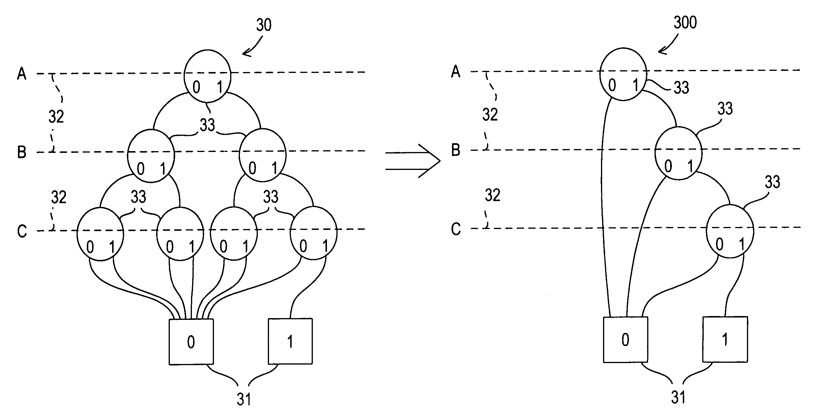
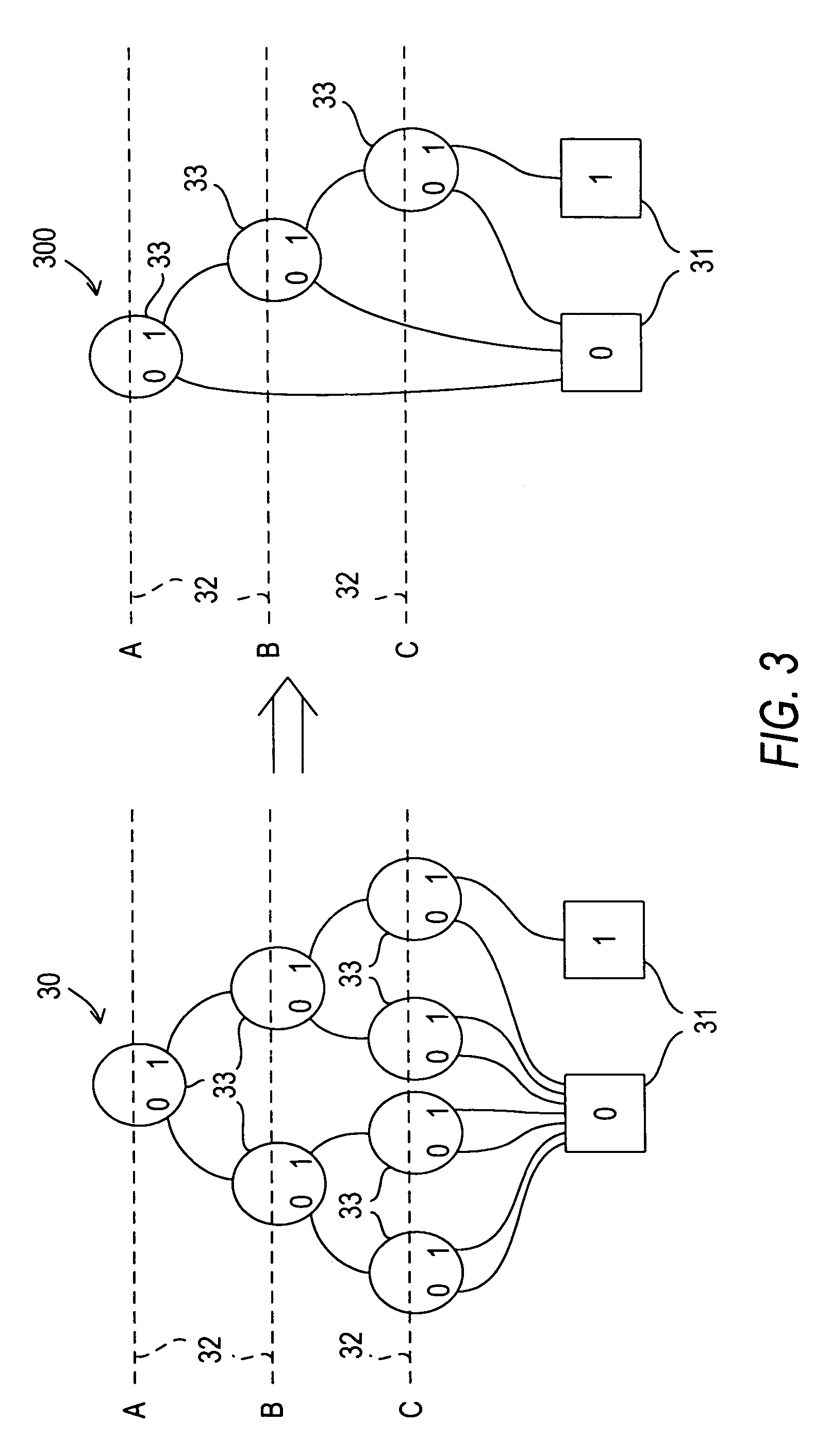
[0028]PLDs of the type with which the present invention may be used are typically based on look-up-table-type logic LEs. For example, LEs in PLDs from Altera Corporation, of San Jose, Calif., typically are based on 4-input look-up tables (4-input “LUTs” or “4-LUTs”). However, for purposes of illustration, it is less cumbersome to consider a 3-input look-up table (“3-LUT”), which may be represented logically by half the number of components as compared to a 4-LUT.

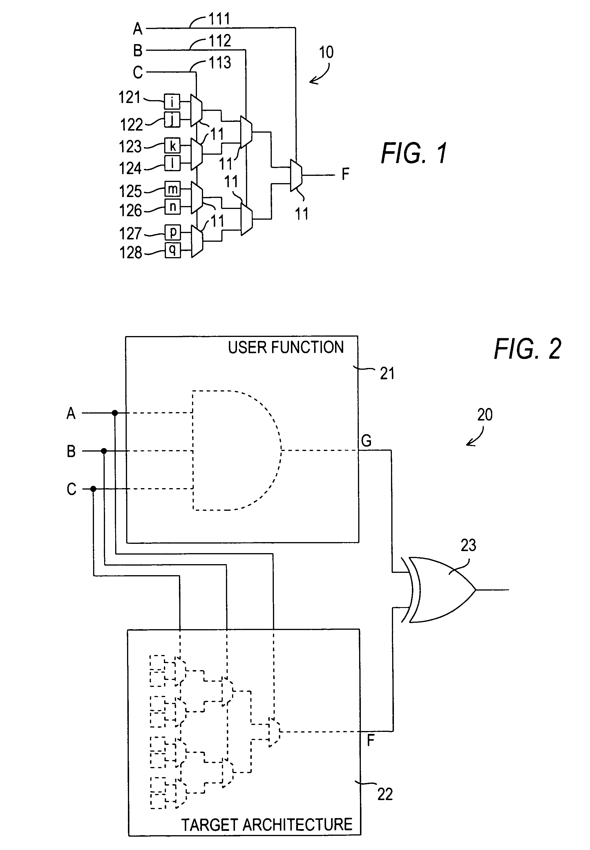
[0029]FIG. 1 shows an LE 10 as a 3-LUT represented logically as a logic cone or tree of seven 2:1 multiplexers 11, with the multiplexer control inputs being the look-up table inputs A (111), B (112), C (113), and the multiplexer data inputs being the PLD configuration bits i, j, k, l, m, n, p, q 121-128. The “vector” of values of configuration bits 121-128 is sometimes referred to as the “LUTmask” of the LUT or LE.

[0030]The truth table for LE 10, in terms ...


PUM


Abstract

A programmable logic device (“PLD”) architecture and a user logic design are modeled logically to find an efficient programming solution for the user logic design on the PLD architecture. The logical models are converted to equations—e.g., by representing them as binary decision diagrams which can be modeled and manipulated mathematically with commercially available tools. The equations can be solved for the programming or configuration variables. Similarly, an efficient programmable logic device architecture for implementing one or more of a given set of logic functions can be found by mapping each function in the set of functions onto a generic architecture and solving for the configuration variables. By comparing the results for all functions, one can reduce the generic architecture to an efficient architecture for that set of functions by eliminating structures from the generic architecture whose configuration bits are the same for all solutions.

Description

BACKGROUND OF THE INVENTION[0001]This invention relates to the use of technology mapping for programming or designing a programmable logic device (“PLD”). In particular, this invention relates to using logical equivalency checking to find more efficient programming solutions for implementing user logic in a programmable logic device of a particular architecture, and also to find a more efficient architecture to implement a particular logical problem.[0002]Programmable logic devices are well known. Early programmable logic devices were one-time configurable. For example, configuration may have been achieved by “blowing”—i.e., opening—fusible links. Alternatively, the configuration may have been stored in a programmable read-only memory. Those devices generally provided the user with the ability to configure the devices for “sum-of-products” (or “P-TERM”) logic operations. Later, such programmable logic devices incorporating erasable programmable read-only memory (EPROM) for configura...

Claims


Application Information

Patent Timeline
Patent Type & Authority Patents(United States)
IPC IPC(8): G06F17/50
CPCG06F17/5054G06F30/34
Inventor PERRY, STEVEN
Owner ALTERA CORP
Why Eureka
Try Eureka