Laser scanning system for object monitoring

a scanning system and object technology, applied in the field of optical systems for monitoring the motion, can solve the problems of inability to detect objects, and inability to detect objects, and achieve the effect of rapid high-resolution data

Inactive Publication Date: 2008-04-22
UT BATTELLE LLC
View PDF13 Cites 24 Cited by
  • Summary
  • Abstract
  • Description
  • Claims
  • Application Information

AI Technical Summary

Benefits of technology

[0022]It is another object of the invention to provide a laser scanning system with substantially increased information bandwidth.
[0024]In a laser scanning system, it is another object to provide means for improving the reliability of information received from retroreflectors associated with monitored objects.
[0025]In a laser scanning system, it is another object to provide means for improving the reliability of the scanner / retroreflector link itself.
[0028]In a laser scanning system, it is another object to scan fixed targets in a point-to-point manner that enables very high resolution data to be obtained rapidly.
[0029]In a laser scanning system, it is another object to provide a data collection methodology that, while producing high resolution data, creates manageable data sets.

Problems solved by technology

The objections arise from the fundamental nature of RF transmissions.
It also suggests the possibility for third-party interception of the data transmissions, which may represent an unacceptable security risk or political irritant.
In addition, there are some environments, particularly where explosive atmospheres or high explosives are present, in which RF transmissions may pose a prohibitive physical safety hazard.
A feature of laser scanning systems is that remote third party interception of the optical transmissions can become virtually impossible because interception of the transmissions require some physical access to the line-of-sight optical beam between the transmitter and receiver.

Method used


Image

  • Laser scanning system for object monitoring
  • Laser scanning system for object monitoring
  • Laser scanning system for object monitoring

Examples


Embodiment Construction

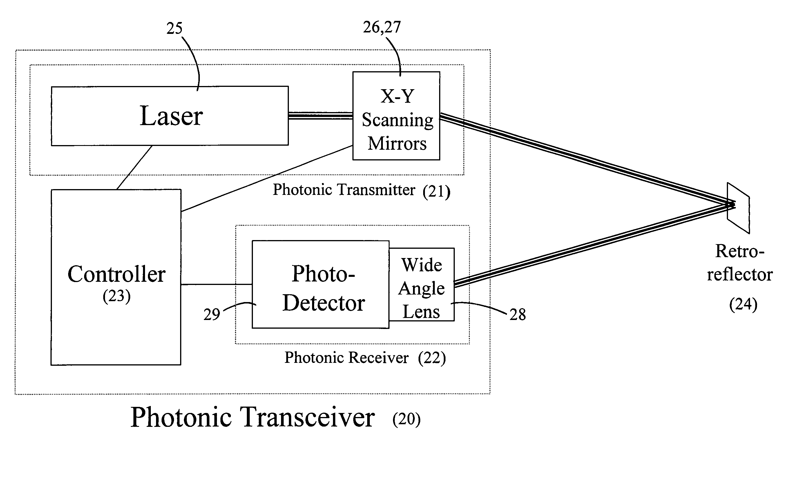
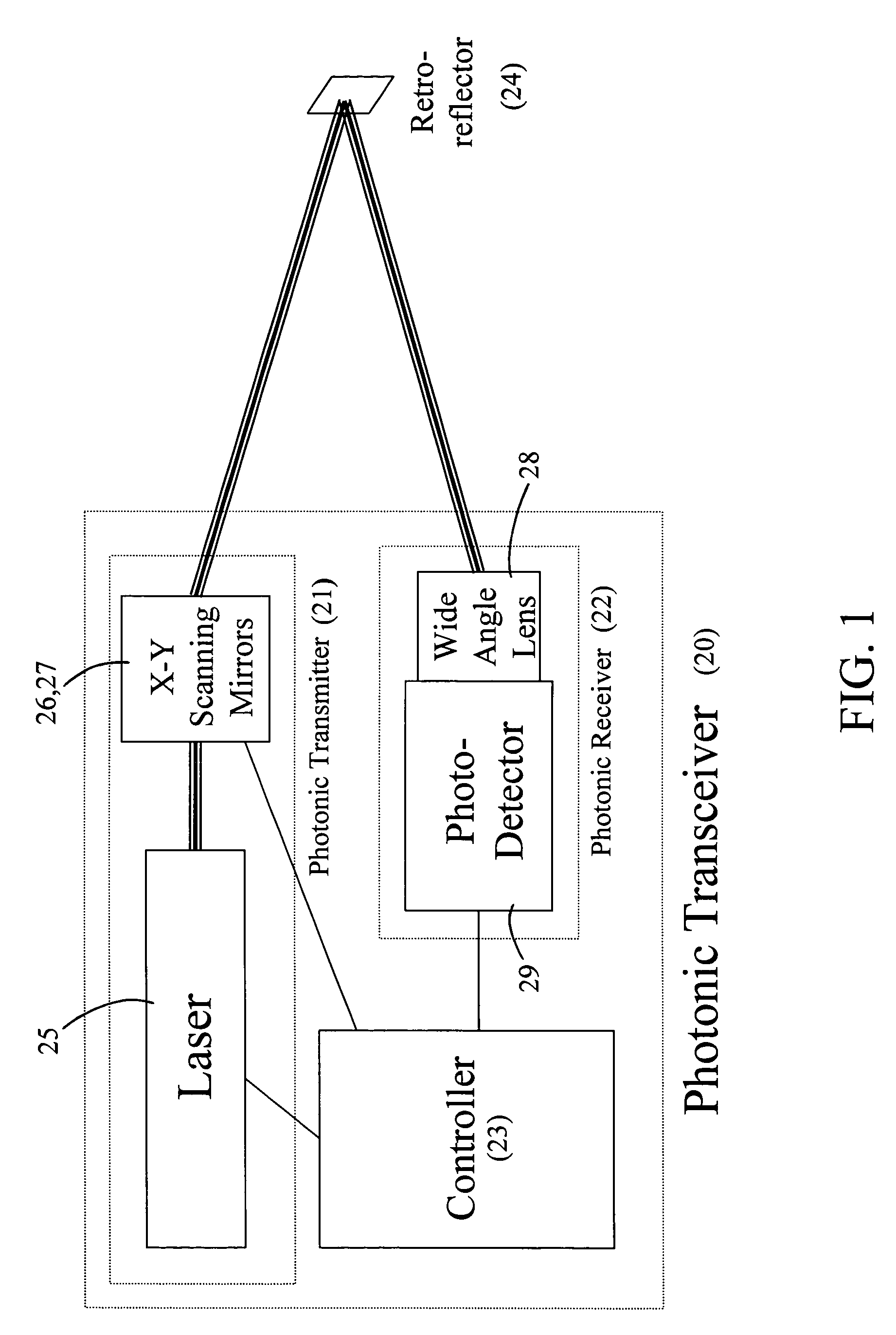
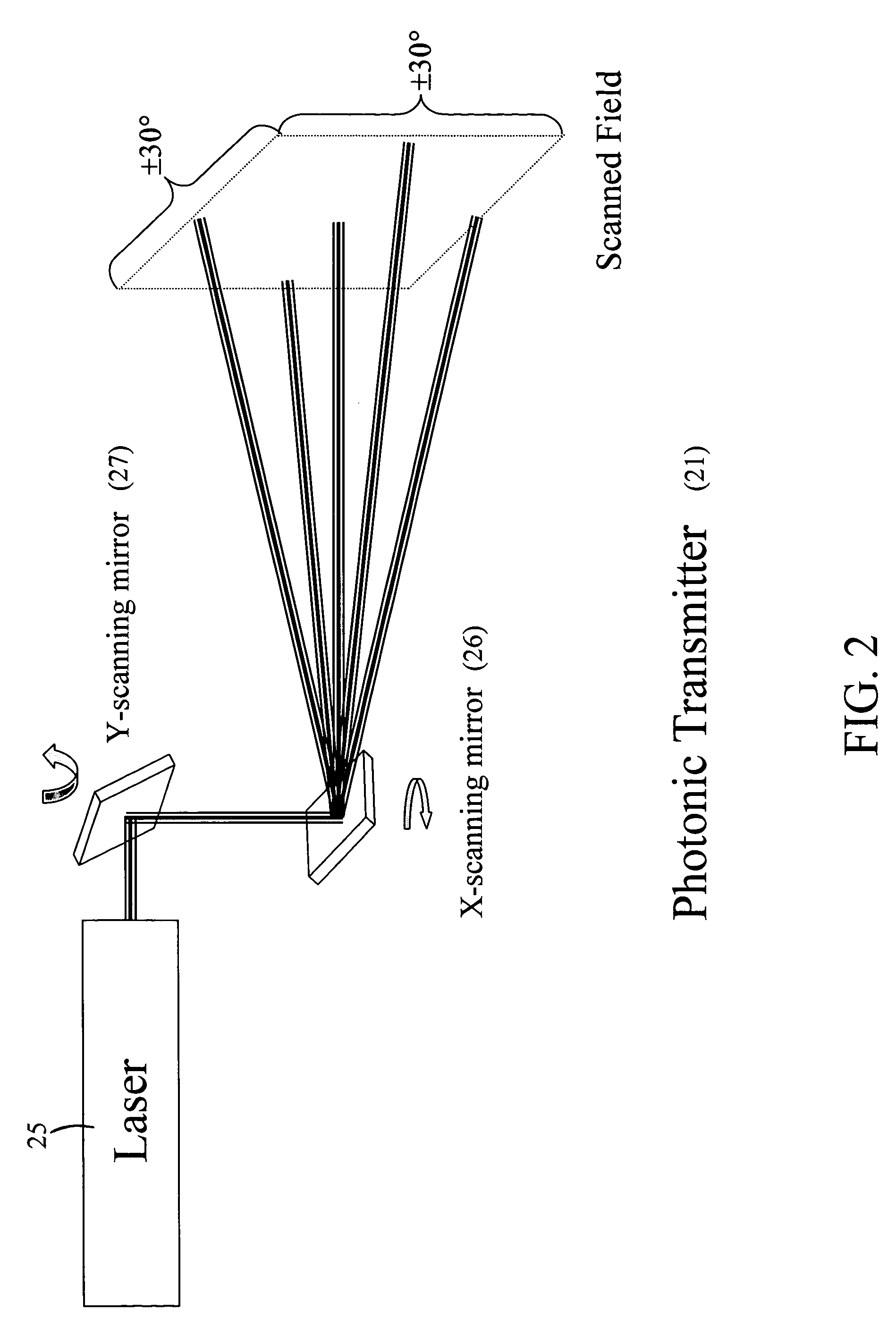
[0052]In FIG. 1, the laser scanning system of our invention includes at least one photonic transceiver 20 that comprises a photonic transmitter 21, a photonic receiver 22, and a controller 23. The photonic transmitter 21 directs laser light to one or more retroreflecting targets 24. The photonic transmitter 21 shown in FIG. 2 includes a means for steering the laser beam to a multiplicity of targets in the scanned field. The steering range is generally limited to ±30° from normal, in both the horizontal and vertical directions, and is accomplished via galvanometer controlled rotating mirrors 26, 27. The device used for rotating the mirrors 26, 27 may be a Cambridge Technology 2-D scanning mirror device model 6350, for example. Once the laser beam has been directed to a retroreflective target, the target returns a diffuse cone of light 30 as shown in FIG. 3. Depending upon the characteristics of the retroreflective target 24, the distribution of returned light energy may vary as a fun...


PUM


Abstract

A laser scanner is located in a fixed position to have line-of-sight access to key features of monitored objects. The scanner rapidly scans pre-programmed points corresponding to the positions of retroreflecting targets affixed to the key features of the objects. The scanner is capable of making highly detailed scans of any portion of the field of view, permitting the exact location and identity of targets to be confirmed. The security of an object is verified by determining that the cooperative target is still present and that its position has not changed. The retroreflecting targets also modulate the reflected light for purposes of returning additional information back to the location of the scanner.

Description

STATEMENT REGARDING FEDERALLY SPONSORED RESEARCH OR DEVELOPMENT[0001]The United States Government has rights in this invention pursuant to Contract No. DE-AC05-00OR22725 between the United States Department of Energy and UT-Battelle, LLC.BACKGROUND OF THE INVENTION[0002]1. Field of the Invention[0003]The invention is related to optical systems for monitoring the motion of objects. In particular, increased information bandwidth is achieved in a laser scanning transceiver system through the use of a noncommon collection path for the return light from retroreflectors located on the monitored objects.[0004]2. Description of Prior Art[0005]Wireless monitoring systems, whether based on optical or radio frequency (RF) technologies, are used in many applications where it is desired to monitor the movement of large structures, vehicles or groups of stationary objects. The purpose is to measure the position and / or disturbance to that position of tags located on objects, and to do so with a sc...

Claims


Application Information

Patent Timeline
Patent Type & Authority Patents(United States)
IPC IPC(8): G06K7/10
CPCH04B10/112
Inventor MCINTYRE, TIMOTHY JAMESMAXEY, LONNIE CURTISCHIARO, JR., PETER JOHN
Owner UT BATTELLE LLC
Why Eureka
Try Eureka