Gas turbine engines seal assembly and methods of assembling the same

a technology of gas turbine engines and seals, which is applied in the direction of machines/engines, liquid fuel engines, forging/pressing/hammering apparatus, etc., can solve the problems of relatively high forward axial load of the turbine, relatively difficult to achieve in a typical hpcc rotor-stator cavity, and inability to balance axial load, so as to reduce axial force, and facilitate reducing cavity pressure

Active Publication Date: 2008-04-29
GENRERAL ELECTRIC CO
View PDF11 Cites 16 Cited by
  • Summary
  • Abstract
  • Description
  • Claims
  • Application Information

AI Technical Summary

Benefits of technology

[0005]In one aspect, a method of assembling a gas turbine engine is provided. The method includes providing a gas turbine engine including a compressor, a combustor downstream from the compressor, and a turbine coupled to the compressor, and coupling a seal assembly aft of the compressor such that air discharged through the seal assembly facilitates reducing the cavity pressure, and therefore reducing the axial forces induced to an aft side of the compressor.
[0006]In another aspect, a seal assembly for a gas turbine engine is provided. The seal assembly includes a labyrinth seal assembly that is coupled aft of the centrifugal compressor such that air discharged through the seal assembly facilitates reducing the cavity pressure, and therefore reducing the axial forces induced to an aft side of the centrifugal compressor.
[0007]In a further aspect, a gas turbine engine assembly is provided. The gas turbine engine assembly includes a centrifugal compressor, a combustor downstream from the centrifugal compressor, a turbine coupled to the compressor, and a seal assembly coupled aft of the centrifugal compressor such that air discharged through the seal assembly facilitates reducing the cavity pressure, and therefore reducing the axial forces induced to an aft side of the centrifugal compressor.

Problems solved by technology

Gas turbine engines with multiple stage compressors and turbines may somewhat result in a balance axial load.
However, utilizing a single stage HPCC, wherein the HPCC radius is larger than the turbine radius, may result in a relatively high forward axial load on the turbine.
However, this is relatively difficult to achieve in a typical HPCC rotor-stator cavity due to stator drag and limitations on flow for operability.
As a result, pressure decreases may be realized at primarily at low radii with high flowing systems resulting in relatively small changes in load.

Method used


Image

  • Gas turbine engines seal assembly and methods of assembling the same
  • Gas turbine engines seal assembly and methods of assembling the same
  • Gas turbine engines seal assembly and methods of assembling the same

Examples


Embodiment Construction

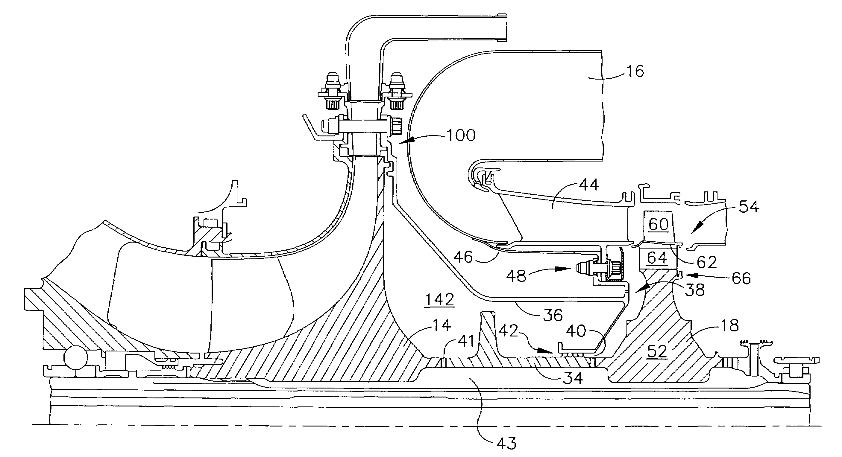
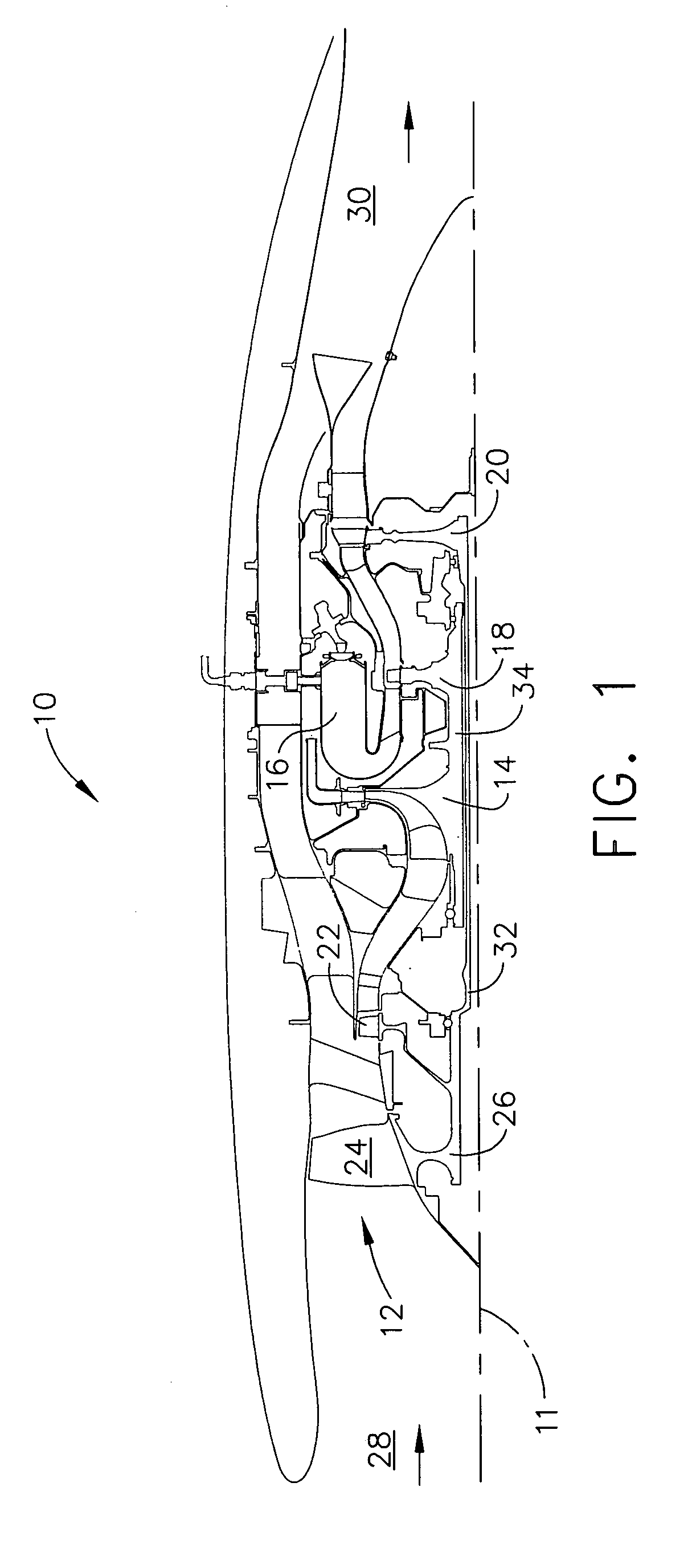
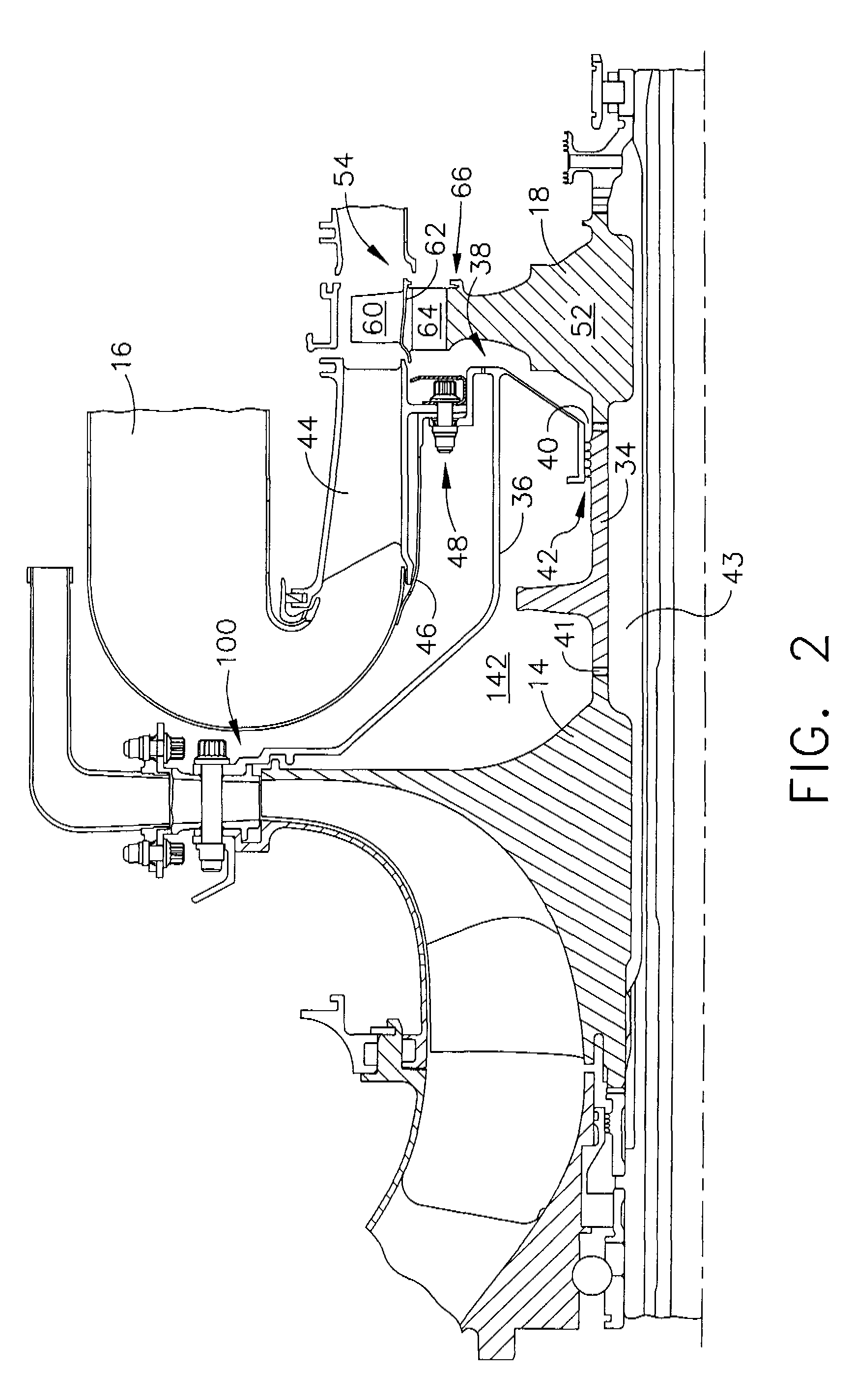
[0013]FIG. 1 is a schematic illustration of an exemplary gas turbine engine assembly 10 having a longitudinal axis 11. Gas turbine engine assembly 10 includes a fan assembly 12, a high-pressure centrifugal compressor 14, and a combustor 16. Engine 10 also includes a high-pressure turbine assembly 18, a low-pressure turbine 20, and a booster compressor 22. Fan assembly 12 includes an array of fan blades 24 extending radially outward from a rotor disk 26. Engine 10 has an intake side 28 and an exhaust side 30. Fan assembly 12, booster 22, and low-pressure turbine 20 are coupled together by a first rotor shaft 32, and compressor 14 and high-pressure turbine assembly 18 are coupled together by a second rotor shaft 34. Although gas turbine engine assembly 10 is shown in the exemplary embodiment including a single stage centrifugal compressor 14 and a single stage high-pressure turbine 18, it should be realized that compressor 14 and turbine 18 may include a plurality of stages.

[0014]In o...


PUM

PropertyMeasurementUnit
pressureaaaaaaaaaa
diameteraaaaaaaaaa
diametersaaaaaaaaaa

Abstract

A method of assembling a gas turbine engine includes providing a gas turbine engine including a compressor, a combustor downstream from the compressor, and a turbine coupled to the compressor, and coupling a seal assembly aft of the compressor such that air discharged through the seal assembly facilitates reducing the cavity pressure, and therefore reducing the axial forces induced to an aft side of the compressor.

Description

BACKGROUND OF THE INVENTION[0001]This invention relates generally to gas turbine engines and, more particularly, to methods and apparatuses for reducing thrust bearing net axial load caused by pressurized rotor-stator cavities.[0002]Gas turbine engine rotor blades typically include a compressor, a combustor, and a high-pressure turbine. In operation, air flows through the compressor and the compressed air is delivered to the combustor wherein the compressed air is mixed with fuel and ignited. The heated airflow is then channeled through the high-pressure turbine to facilitate driving the compressor.[0003]More specifically, High Pressure Centrifugal Compressors (HPCC) may contribute a relatively high percentage of the axial load to a high-pressure rotor thrust bearing. Gas turbine engines with multiple stage compressors and turbines may somewhat result in a balance axial load. However, utilizing a single stage HPCC, wherein the HPCC radius is larger than the turbine radius, may resul...

Claims


Application Information

Patent Timeline
Patent Type & Authority Patents(United States)
IPC IPC(8): F01D3/04
CPCF01D11/02F02C3/08Y10T29/4932Y10T29/49895Y10T29/49323F04D29/0516F04D29/083F04D29/284
Inventor MONTGOMERY, JULIUS JOHNPROCTOR, ROBERTCORMIER, NATHAN GERARDGLYNN, CHRISTOPHER CHARLESROYAL, GLEN WILLIAM
Owner GENRERAL ELECTRIC CO
Why Eureka
Try Eureka