Active sensor for micro force measurement

a micro-force sensor and active technology, applied in the field of micromanipulation technology, can solve the problems of inefficient assembly process of micro devices, inability to reliably measure breakage at the micro-newton force range, and inability to develop efficient assembly processes for micro devices, etc., to achieve fast balance of deformation, improve sensor stiffness, and improve the effect of accuracy

Inactive Publication Date: 2008-05-06
BOARD OF TRUSTEES OPERATING MICHIGAN STATE UNIV
View PDF10 Cites 27 Cited by
  • Summary
  • Abstract
  • Description
  • Claims
  • Application Information

AI Technical Summary

Benefits of technology

[0004]In accordance with the present invention, an improved active micro-force sensor is provided for use on a micromanipulation device. The active micro-force sensor includes a cantilever structure having an actuator layer of piezoelectric material and a sensing layer of piezoelectric material symmetrically bonded together. When an external force is exerted on the sensor tip, the sensor beam deforms and an applied force signal is detected by the sensing layer. The applied force signal is then fed back to the actuating layer of the sensor via a servoed transfer function or servo controller so that a counteracting deformation can be generated by the bend moment from the servoed actuating layer to quickly balance the deformation caused by the external micro-force. Once balanced, the sensor beam comes back to straight status and the tip will remain in its equilibrium position, thus the sensor stiffness seems to be virtually improved so that the accurate motion control of the sensor tip can be reached, especially, at the same time, the micro-force can also be obtained by solving the counteracting balance voltage applied to the actuating layer.

Problems solved by technology

Efficient assembly processes for micro devices have not been developed, partially because, at the micro-scale, structures are fragile and easily breakable.
Typically breakage at the micro-Newton force range cannot be reliably measured by most existing force sensors.
This method can be inherently risky without an on-line safety micro force regulation.
As a result, this approach decreases overall yield and drives up the cost of micro devices.
However, cantilever-based sensors introduce significant limitations for micro-force measurements during micromanipulation.
First, the cantilever-based sensors have a relatively flexible structure which causes inherent difficulties with accurate manipulation of micro devices.
Second, such sensors exhibit only a small dynamic range for maintaining high accuracy.

Method used


Image

  • Active sensor for micro force measurement
  • Active sensor for micro force measurement
  • Active sensor for micro force measurement

Examples


Embodiment Construction

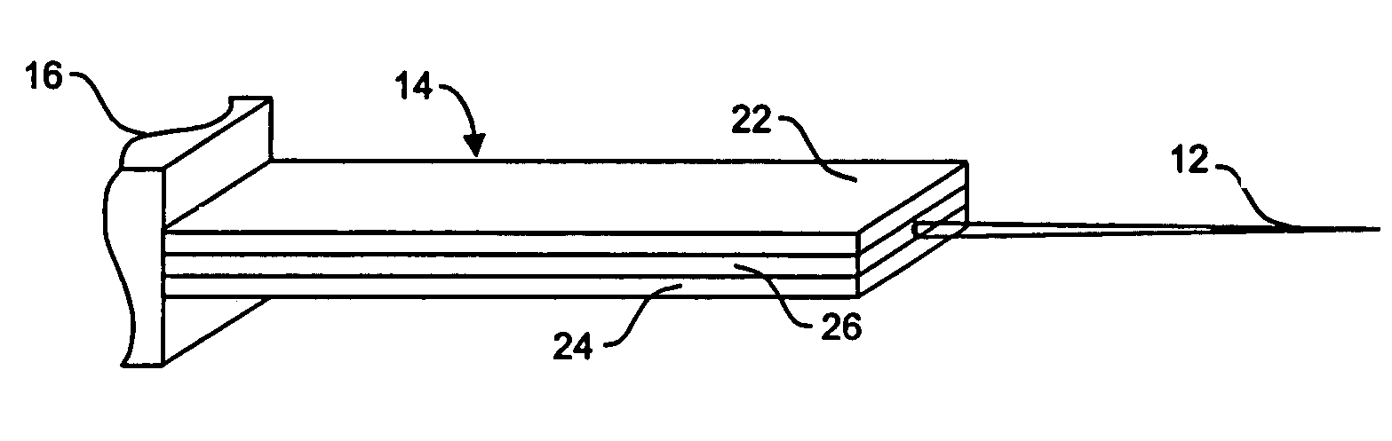
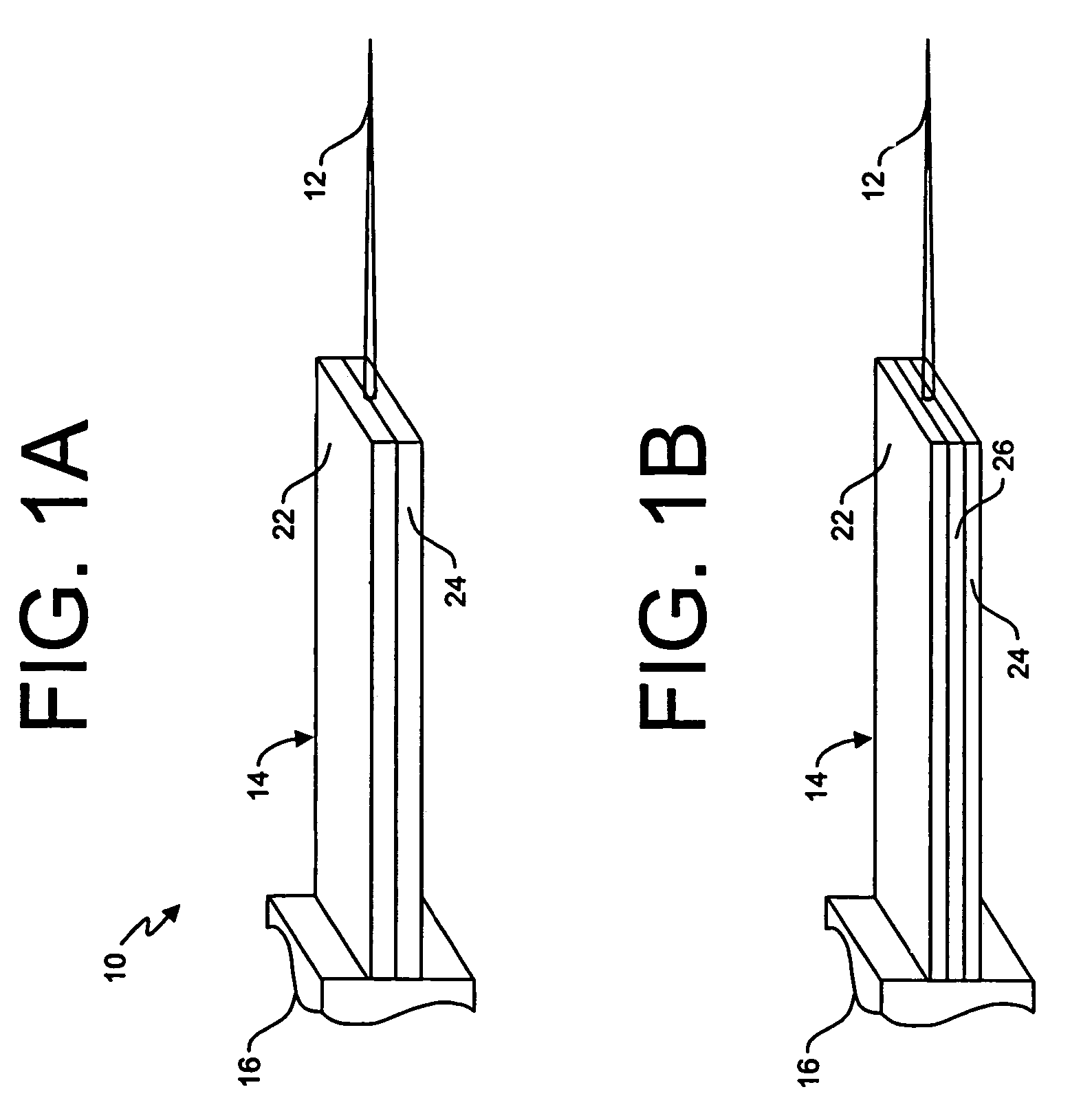
[0012]FIGS. 1A and 1B illustrates an active micro-force sensor for use on a micromanipulation device. The force sensor 10 is comprised of a rigid contact tip 12 which extends outwardly from a cantilever 14. The cantilever 14 is in turn coupled to an end of a micromanipulator 16. It is readily understood that the contact tip 12 may have different shapes depending on the applicable micromanipulation tasks.

[0013]In accordance with the present invention, the cantilever 14 is a composite structure having at least two layers 22, 24 made from a piezoelectric material (e.g., polyvinylidene fluoride (PVDF) or lead zirconate titanate (PZT)). In operation, the top layer 22 acts as a balance actuator, while the bottom layer 24 works as a sensing device as will be further explained below.

[0014]In FIG. 1A, the two layers 22, 24 are bonded directly together using an insulating, waterproof, high strength, and elastic adhesive (e.g. Loctite® Super Glue Gel, Epoxy Gel or RTV Silicone) or other known ...


PUM

PropertyMeasurementUnit
input impedanceaaaaaaaaaa
frequencyaaaaaaaaaa
loop timeaaaaaaaaaa

Abstract

An active micro-force sensor is provided for use on a micromanipulation device. The active micro-force sensor includes a cantilever structure having an actuator layer of piezoelectric material and a sensing layer of piezoelectric material bonded together. When an external force is exerted on the sensor, the sensor deforms and an applied force signal is recorded by the sensing layer. The applied force signal is then fed back to the actuating layer of the sensor via a servoed transfer function or servo controller, so that a counteracting deformation can be generated by the bending moment from the servoed actuating layer to quickly balance the deformation caused by the external micro-force. Once balanced, the sensor beam comes back to straight status and the tip will remain in its equilibrium position, thus the sensor stiffness seems to be virtually improved so that the accurate motion control of the sensor tip can be reached, especially, at the same time, the micro-force can also be obtained by solving the counteracting balance voltage applied to the actuating layer.

Description

FIELD OF THE INVENTION[0001]The present invention relates generally to micromanipulation technology and, more particularly, to an active micro-force sensor for use in micromanipulation.BACKGROUND OF THE INVENTION[0002]Efficient assembly processes for micro devices have not been developed, partially because, at the micro-scale, structures are fragile and easily breakable. Typically breakage at the micro-Newton force range cannot be reliably measured by most existing force sensors. So far the most straightforward and flexible operation methods run in an open loop format using a microprobe to physically manipulate the micro device. This method can be inherently risky without an on-line safety micro force regulation. As a result, this approach decreases overall yield and drives up the cost of micro devices. For these reasons, research into automating the micromanipulation processes have focused on micro force sensing and related control techniques.[0003]In micro force sensing, cantileve...

Claims


Application Information

Patent Timeline
Patent Type & Authority Patents(United States)
IPC IPC(8): G01L1/10
CPCG01L1/08
Inventor XI, NINGSHEN, YANTAO
Owner BOARD OF TRUSTEES OPERATING MICHIGAN STATE UNIV
Why Eureka
Try Eureka