Snubbers for low temperature power electronics

Inactive Publication Date: 2008-05-06
MTECH LAB
View PDF2 Cites 3 Cited by
  • Summary
  • Abstract
  • Description
  • Claims
  • Application Information

AI Technical Summary

Benefits of technology

[0004]Concepts have recently been developed whereby switching losses and conduction losses are isolated by networks which are partially cryogenic and partially at room temperature. The switching losses are independent of temperature, so it is advantageous to take the switching losses at room temperature and to incur the conduction losses at cryogenic temperatures, wh

Problems solved by technology

This circuitry costs energy due to the joule heating of the snubber network.
At cryogenic temperatures this can lead to large losses amplified by the refrigeration factor.
High performance cryogenic solid-state switches such as MOSFETs operated at l

Method used


Image

  • Snubbers for low temperature power electronics
  • Snubbers for low temperature power electronics
  • Snubbers for low temperature power electronics

Examples


Embodiment Construction

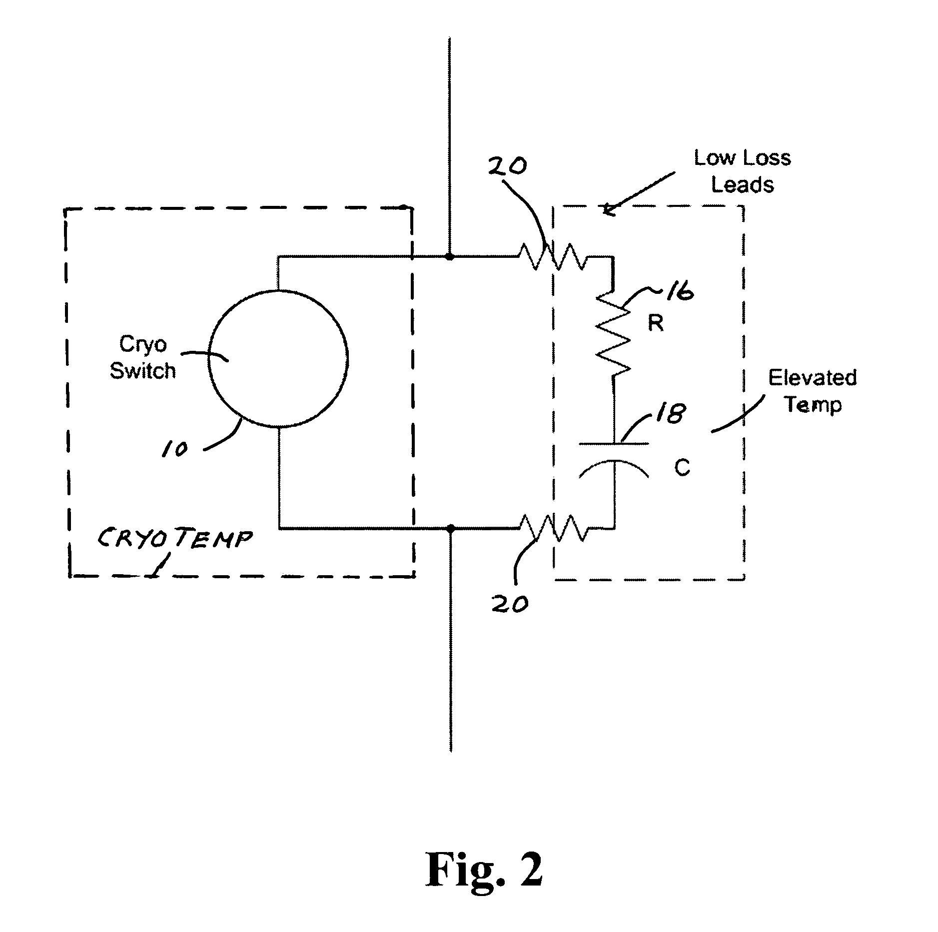
[0009]In one construction to reduce dissipation in cryogenically operated power devices, snubbers are added at room temperature with low inductance interconnecting leads, as shown in FIG. 2. There the switch 10 operates with high speed at cryogenic temperature and the snubber network 16, 18 operates at a higher temperature e.g. room temperature. The leads 20, having cold ends and warmer ends, connect the switch and snubber network. This network absorbs most of the load current as the switch opens. For typical snubber network designs the RC time constant is longer than the switching time.

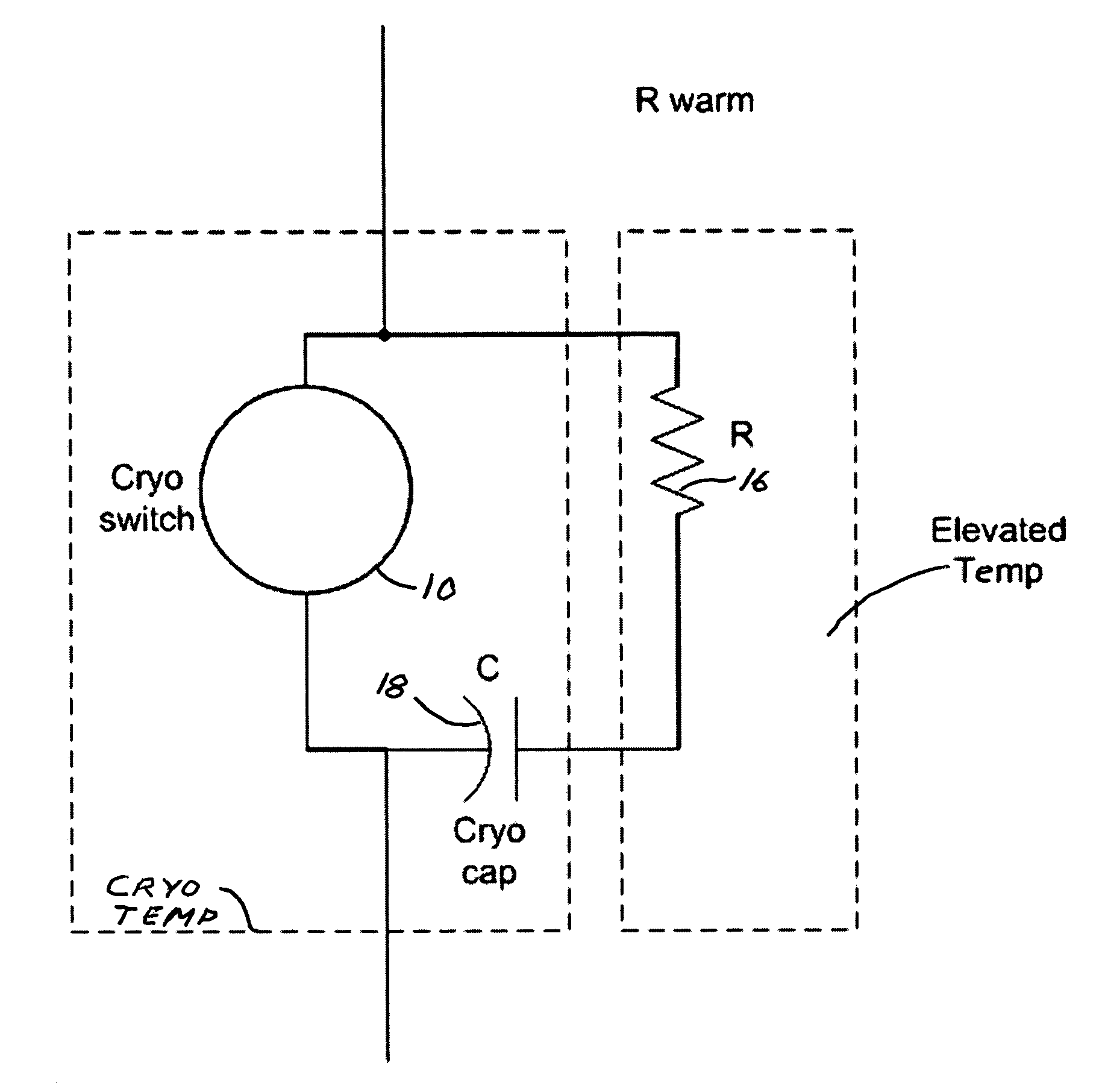
[0010]In some cases it is advantageous to cool the switch 10 and C 18 of the snubber network and to move the R 16 to room temperature as shown in FIG. 3. The choice depends on the available capacitor technology. In some cases, the voltage capability of capacitors increases at cryogenic temperatures, leading to higher energy density and therefore a reduction in size and weight.

[0011]An equivalent circ...


PUM


Abstract

Switching losses and conduction losses are isolated by networks which are partially cryogenic and partially at room temperature. Switching losses are independent of temperature. Advantageously the switching losses are taken in a snubber network at room temperature and conduction losses are incurred at cryogenic temperatures, where majority carrier devices like MOSFETs operate with ultra low on-state resistance and corresponding low conduction losses. Low loss leads carry current efficiently from the cryogenic environment to room temperature without adversely affecting refrigeration. Switch and snubber network may both operate cryogenically.

Description

[0001]This patent application claims the benefit of provisional patent application 60 / 609,169, filed Sep. 11, 2004.BACKGROUND OF THE INVENTION[0002]Snubber circuits are routinely used to reduce the dV / dt across switching networks and to reduce ringing. This is usually done with series RC networks placed in parallel with the switch as shown in FIG. 1. There an electronic switch 10 is in series with a source impedance 12 and a load impedance 14 across a voltage input Vo to ground. A snubber network, including a resistance R 16 in series with a capacitor C 18, is in parallel with the switch 10. This circuitry costs energy due to the joule heating of the snubber network. At cryogenic temperatures this can lead to large losses amplified by the refrigeration factor. For example for LN2 systems (liquid nitrogen) the refrigeration factor can approach 12 watts refrigeration per watt of dissipation at 77K.[0003]High performance cryogenic solid-state switches such as MOSFETs operated at low te...

Claims


Application Information

Patent Timeline
IPC IPC(8): H02H7/00H02H9/00H01L23/34H01L29/00
CPCH03K17/92H01L2924/0002H01L2924/00
Inventor HENNESSY, MICHAEL J.PARK, JOHN N.MUELLER, OTWARD M.MUELLER, EDUARD K.
Owner MTECH LAB
Why Eureka
Try Eureka