
Method for resetting pinned layer magnetization in a magnetoresistive sensor

a technology of magnetoresistive sensor and pinned layer, which is applied in the field of resetting self-pinned antiparallel (ap) pinned layer, can solve the problems of troublesome setting the proper polarity of the ap pinned layer next to the free layer, stress-induced anisotropy, and polarity flipping, so as to improve the uniaxial anisotropy field of magnetostriction and high the effect of magnetoresistive coefficient and coefficien

Inactive Publication Date: 2008-05-13
HITACHI GLOBAL STORAGE TECH NETHERLANDS BV
View PDF19 Cites 19 Cited by
  • Summary
  • Abstract
  • Description
  • Claims
  • Application Information

AI Technical Summary

Benefits of technology

"The present invention provides a method for resetting the polarity of a magnetoresistive sensor that has pinned layer mangnetization flipped to the incorrect polarity. The method involves placing the sensor in a high strength magnetic field that is canted with respect to the ABS. The magnetic field can be parallel or at an angle to the ABS. The resetting can be performed at room temperature and after the sensor has been sliced into individual sliders. The invention ensures that sensors are produced with the proper polarity of the pinned layers."

Problems solved by technology

It has been found that during lapping of a row of sliders, mechanical stresses in the sensors cause stress induced anisotropy in the sensor that overcomes the exchange pinning in pinned sensor causing them to flip polarity.
In self pinned sensors, the mechanical stress can cause the magnetostriction induced pinning to be momentarily lost which also leads to polarity flipping.
Setting the proper polarity of the AP pinned layer next to the free layer is troublesome when present prior art techniques are employed.

Method used


Image

  • Method for resetting pinned layer magnetization in a magnetoresistive sensor
  • Method for resetting pinned layer magnetization in a magnetoresistive sensor
  • Method for resetting pinned layer magnetization in a magnetoresistive sensor

Examples


Embodiment Construction

Magnetic Disk Drive

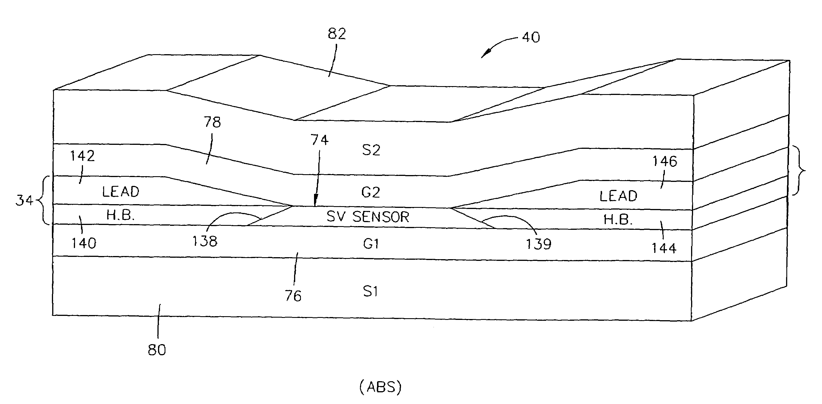
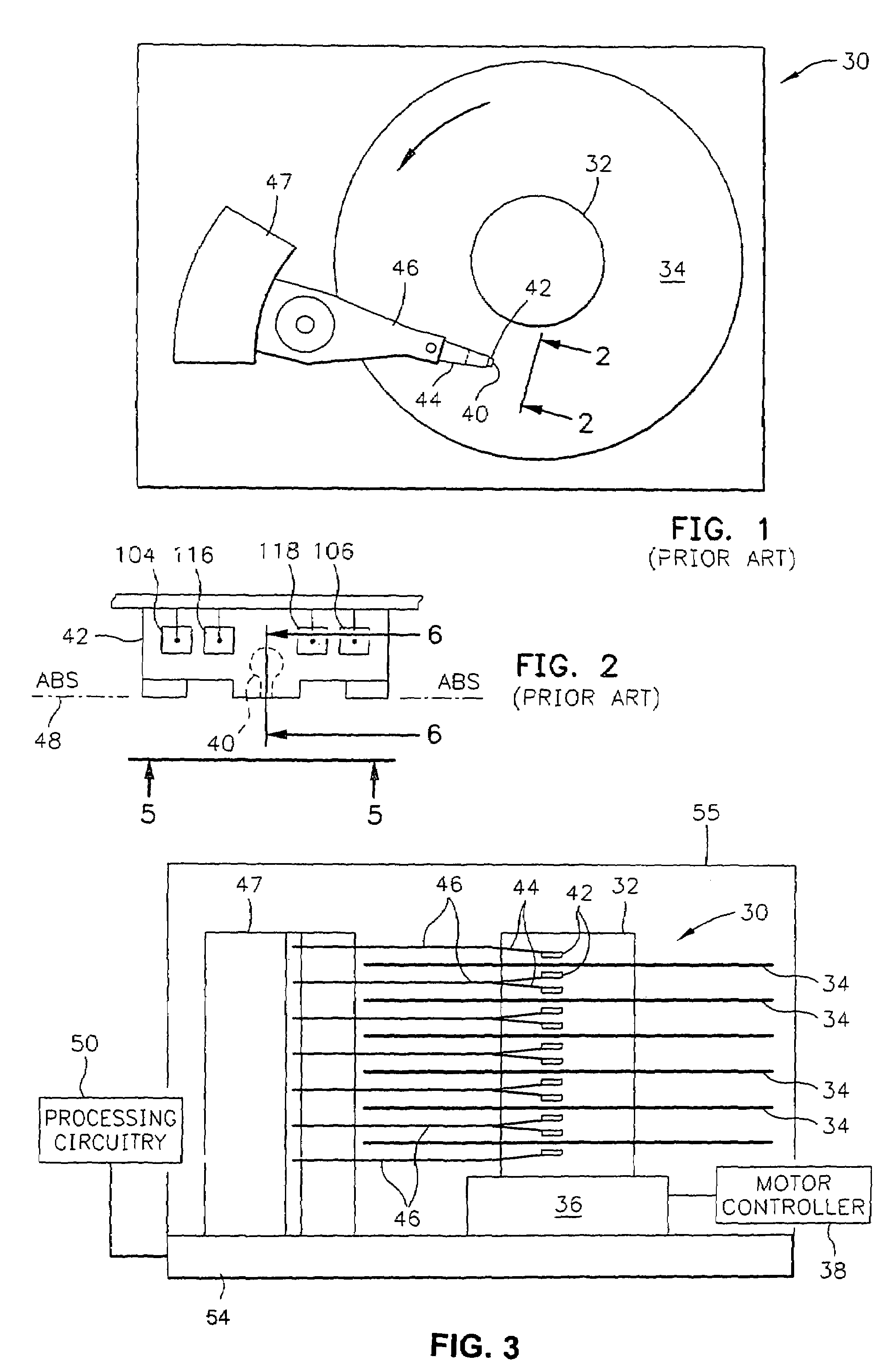
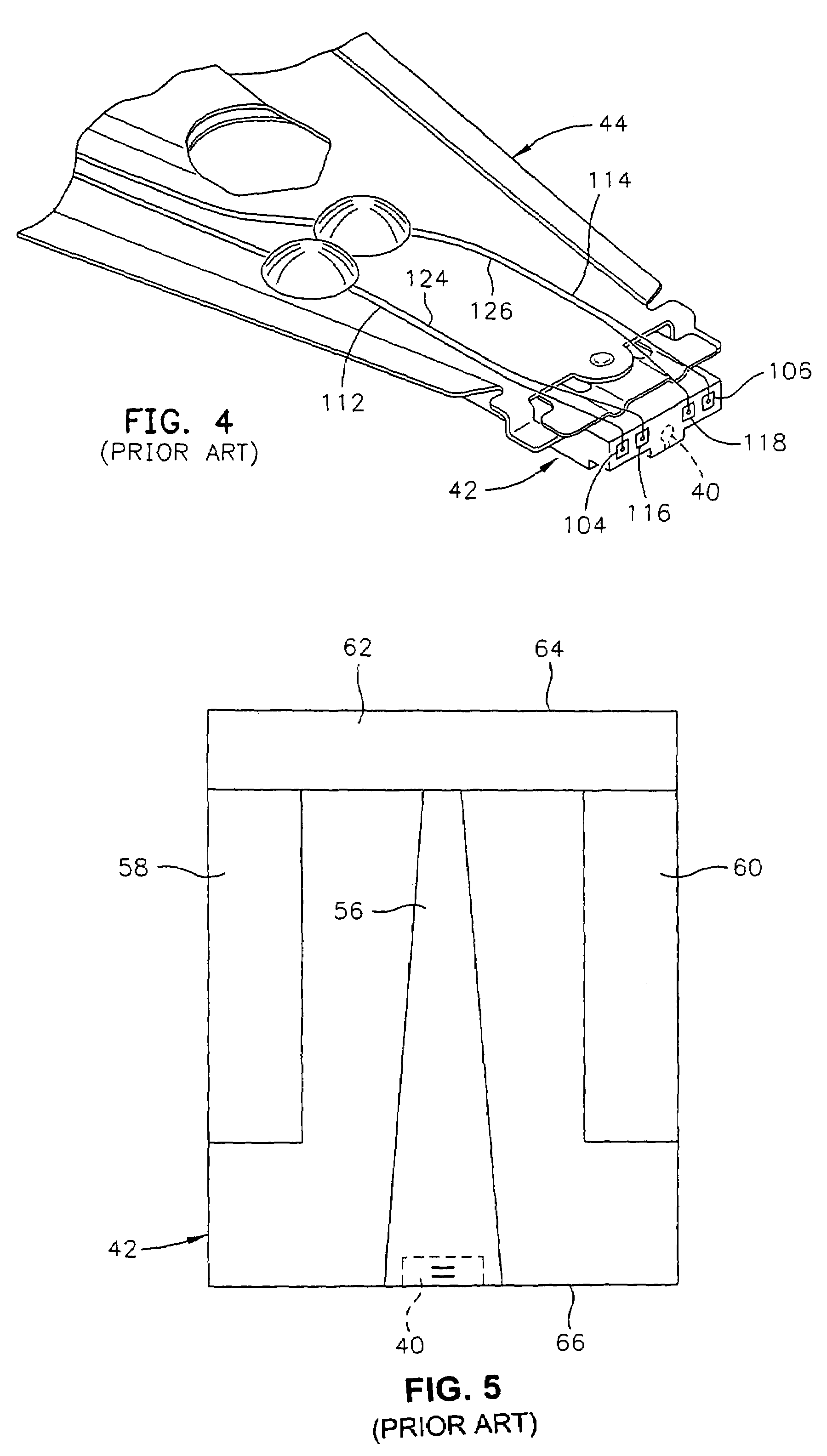
[0045]Referring now to the drawings wherein like reference numerals designate like or similar parts throughout the several views, FIGS. 1-3 illustrate a magnetic disk drive 30. The drive 30 includes a spindle 32 that supports and rotates a magnetic disk 34. The spindle 32 is rotated by a spindle motor 36 that is controlled by a motor controller 38. A slider 42 has a combined read and write magnetic head 40 and is supported by a suspension 44 and actuator arm 46 that is rotatably positioned by an actuator 47. A plurality of disks, sliders and suspensions may be employed in a large capacity direct access storage device (DASD) as shown in FIG. 3. The suspension 44 and actuator arm 46 are moved by the actuator 47 to position the slider 42 so that the magnetic head 40 is in a transducing relationship with a surface of the magnetic disk 34. When the disk 34 is rotated by the spindle motor 36 the slider is supported on a thin (typically, 0.01 μm) cushion of air (air bear...


PUM

PropertyMeasurementUnit
magnetizationaaaaaaaaaa
magnetic fieldaaaaaaaaaa
strengthaaaaaaaaaa

Abstract

A spin valve sensor in a read head has a spacer layer which is located between a self-pinned AP pinned layer structure and a free layer structure. The free layer structure is longitudinally stabilized by first and second hard bias layers which abut first and second side surfaces of the spin valve sensor. The AP pinned layer structure has an antiparallel coupling layer (APC) which is located between first and second AP pinned layers (AP1) and (AP2). The invention employs a resetting process for setting of the magnetic moments of the AP pinned layers by applying a field at an acute angle to the head surface in a plane parallel to the major planes of the layers of the sensor. The resetting process sets a proper polarity of each AP pinned layer, which polarity conforms to processing circuitry employed with the spin valve sensor.

Description

CROSS REFERENCE TO RELATED APPLICATION[0001]This is a Continuation-in-part application of prior application Ser. No. 10 / 104,213 filed on Mar. 21, 2002, now U.S. Pat. No. 6,866,751 designated the United States, the disclosure of which is incorporated herein by reference.BACKGROUND OF THE INVENTION[0002]1. Field of the Invention[0003]The present invention relates to a method of resetting self-pinned antiparallel (AP) pinned layers that have experienced amplitude flipping during manufacturing processes such as lapping. The resetting is accomplished by applying a canted magnetic field and, more particularly, resetting the orientation (polarity) of magnetic moments of such layers by canting a high magnetic field at an acute angle to the air bearing surface (ABS) of a read head in a plane parallel to the major planes of the layers of the read head.[0004]2. Description of the Related Art[0005]The heart of a computer is a magnetic disk drive which includes a rotating magnetic disk, a slider...

Claims


Application Information

Patent Timeline
Patent Type & Authority Patents(United States)
IPC IPC(8): G11B5/127G11B5/00G11B5/31G11B5/39
CPCB82Y10/00B82Y25/00G11B5/3903G11B5/3909G11B5/3163G11B5/3932Y10T29/49032G11B2005/0016G11B2005/3996Y10T29/49021Y10T29/49034Y10T29/49043Y10T29/49044G11B2005/0008
Inventor GILL, HARDAYAL SINGHLI, JINSHANMACKAY, KENNETH DONALDNISHIOKA, KOUICHITRAN, ANDY CUONG
Owner HITACHI GLOBAL STORAGE TECH NETHERLANDS BV
Learn More