Three-dimensional coordinate measuring device

a three-dimensional coordinate and measuring device technology, applied in direction/device determining electromagnetic systems, instruments, television systems, etc., can solve the problems of low accuracy of other devices, slow data collection speed to be used to efficiently determine the coordinates of three-dimensional contours, and low cost of the least expensive device, etc., to achieve convenient movement, easy movement, and rotatable

Active Publication Date: 2008-05-13
FARO TECH INC
View PDF20 Cites 136 Cited by
  • Summary
  • Abstract
  • Description
  • Claims
  • Application Information

AI Technical Summary

Benefits of technology

[0009]An optical camera three-dimensional coordinate measuring system for use with objects to be measured may comprise a compact, easily moveable, and rotatable, target of known dimensions comprising a spherical surface to be placed in direct contact with the object to be measured at different points along the object to be measured thereby eliminating the necessity of using a larger extended probe contact tip extending from the target to the object to be measured; at least one or more light emitting source located in a known position in the target and wherein the light emitting source is located at the spherical center of the target having a spherical surface; at least two cameras located at different and known coordinate locations for receiving light from the light emitting source from different optical perspectives; and a processor for computing the position in three dimensional coordinates of the object to be measured from images of the light emitting source on the cameras, from the known positions of the cameras, from the known dimensions of the target, and from the known position of the light emitting source in the target.
[0011]Another embodiment may comprise an optical camera three-dimensional coordinate measuring method for measuring objects comprising: placing a compact, easily moveable, and rotatable, target of known dimensions comprising a spherical surface in direct contact with the object to be measured at different points along the object to be measured thereby eliminating the necessity of using a larger extended probe contact tip extending from the target to the object to be measured; emitting light from the target form at least one or more light emitting source located in a known position in the target; recording images of the light source at least two cameras located at different and known coordinate locations for receiving light from the light emitting source from different optical perspectives; and computing the position in three dimensional coordinates of the object to be measured from images of the light emitting source on the cameras, from the known positions of the cameras, from the known dimensions of the target, and from the known position of the light emitting source in the target.
[0012]Another embodiment may be an optical camera three-dimensional coordinate measuring system for use with objects to be measured comprising: a compact, easily moveable, and rotatable, target of known dimensions comprising a cylindrical surface to be placed in at least one or more holes in the object to be measured thereby eliminating the necessity of using a larger extended probe contact tip extending from the target to the object to be measured; at least one or more light emitting sources wherein the light emitting source is located at a known position along an axis of cylindrical symmetry; at least two cameras located at different and known coordinate locations for receiving light from the light emitting source from different optical perspectives; and a processor for computing the position in three dimensional coordinates of the object to be measured from images of the light emitting source on the cameras, from the known positions of the cameras, from the known dimensions of the target, and from the known position of the light emitting source in the target.

Problems solved by technology

Today the least expensive of these devices costs nearly $100,000.
Some devices collect data too slowly to be used to efficiency determine the coordinates of three-dimensional contours.
Other devices have relatively poor accuracy.
Such large probes are cumbersome to manage.
Furthermore, the probes need to be stiff and fixed in length over temperature, which means using expensive composite materials.
Thus, it has not been obvious to those skilled in the art that such useful and accurate probes could be devised based on a single point-of-light.

Method used


Image

  • Three-dimensional coordinate measuring device
  • Three-dimensional coordinate measuring device
  • Three-dimensional coordinate measuring device

Examples


fourth embodiment

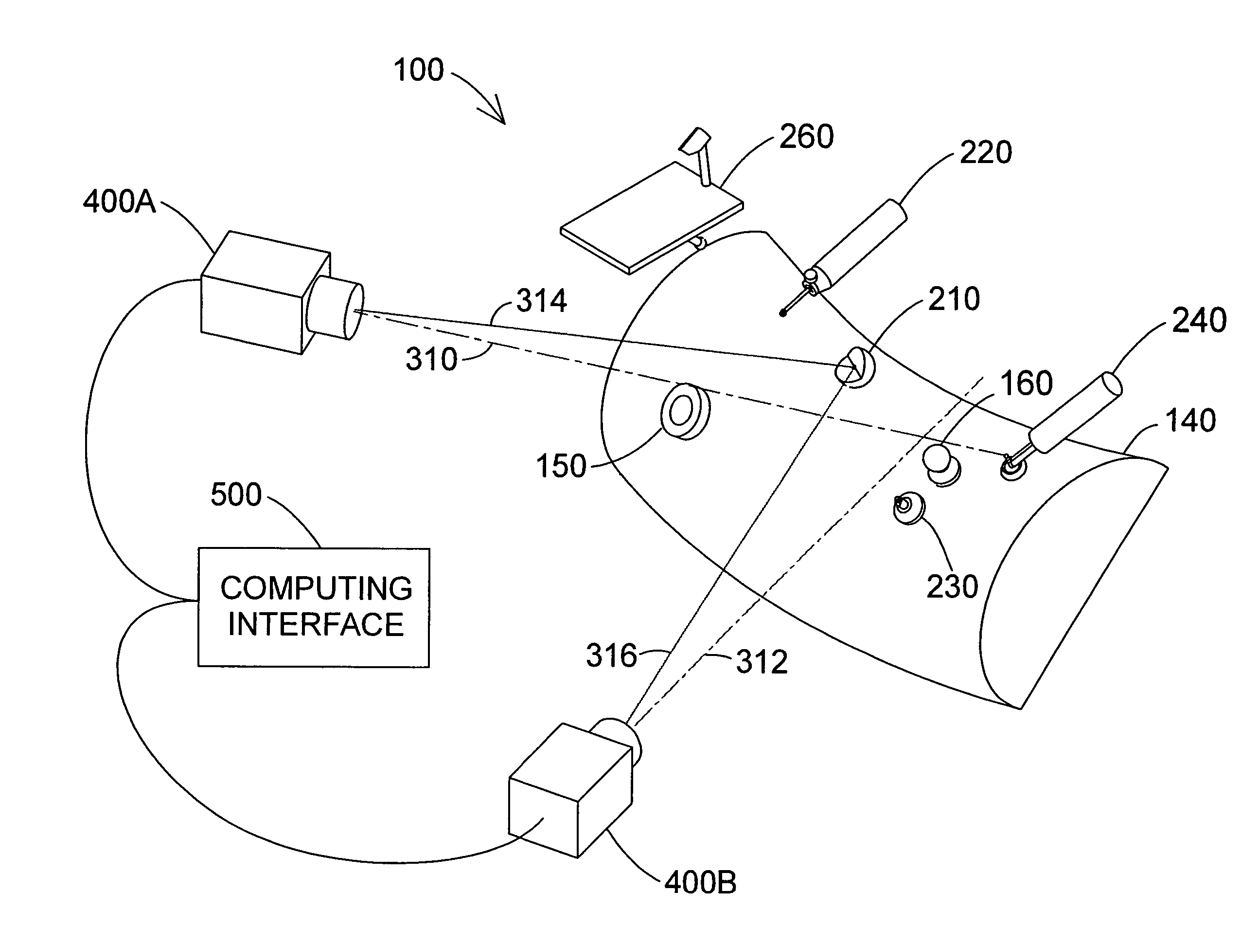
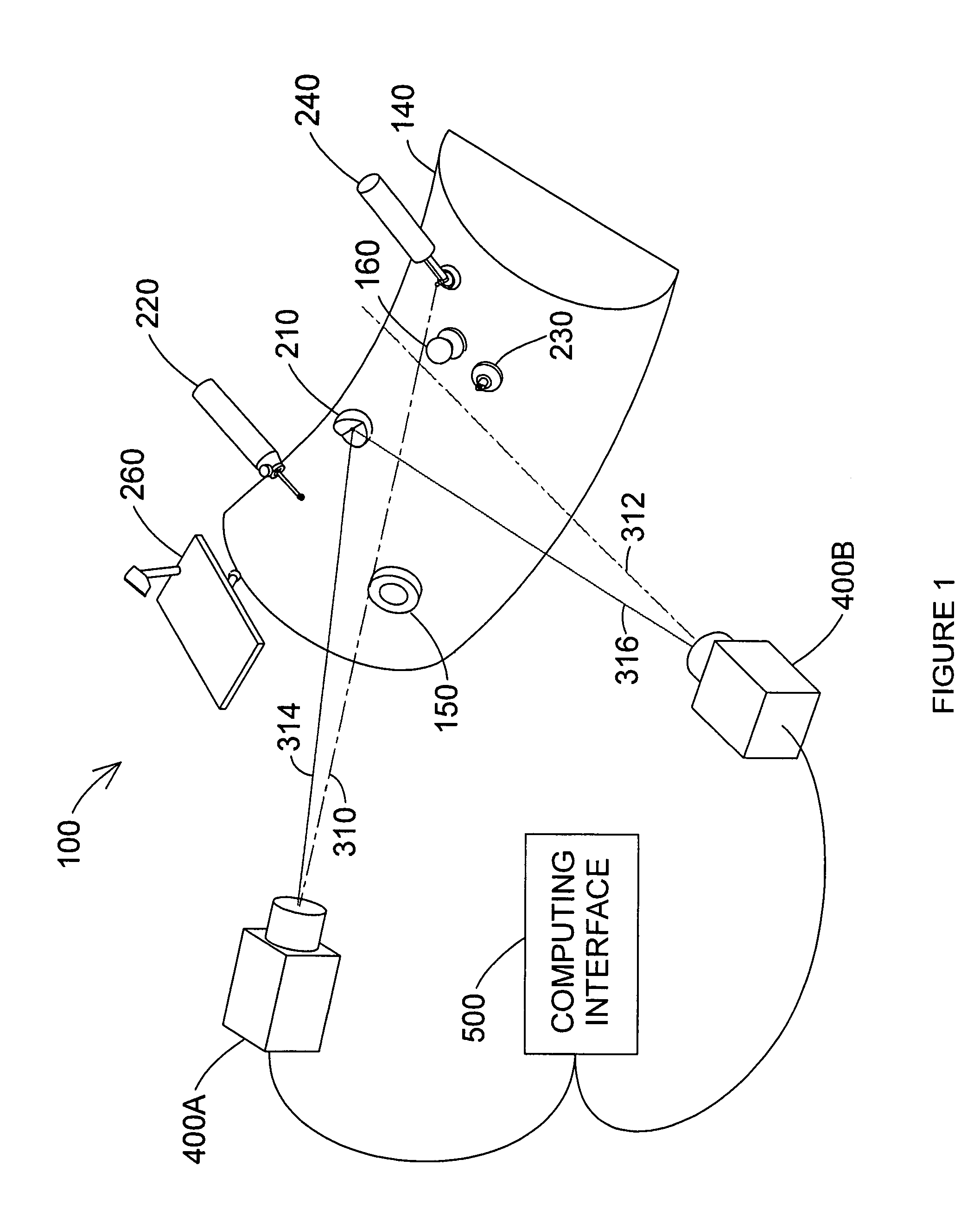
[0032]emitter 200 is the wide-angle emitter 240, shown in perspective view in FIGS. 1 and 5 and in cross-sectional view through the center of the emitter in FIG. 5. Wide-angle emitter 240 comprises emitter ball 250, shaft 242, electronics cavity 244, spherical base segment 246, and optional handle 248. The intensity of light from wide-angle emitter 240 is nearly the same in all directions. Emitter ball 250 is centered on the lower surface of spherical base segment 246. In other words, the distance from the center of emitter ball 250 to the outer surface of spherical base segment 246 is equal to the radius of spherical base segment 246.

[0033]Emitter ball 250, shown in central cross section in FIG. 6(a), comprises upper transparent hemispherical shell 251, lower transparent hemispherical shell 252, and wide-angle light source 255. Upper and lower hemispherical shells 251 and 252 are joined together with index-matching cement to form hollow spherical cavity 253. Spherical cavity 253 is...

fifth embodiment

[0036]emitter 200 is the retroprobe emitter 260, shown in perspective view in FIGS. 1 and 7. Retroprobe emitter 260 comprises light source 261, baffle 262, light source support 263, mirror 264, probe shaft 265, and probe tip 266. Light beam 270 emanates from light source 261, reflects off mirror 264, and travels as light beam 271 to camera 400A. Light beam 272 emanates from light source 261, reflects off mirror264, and travels as light beam 273 to camera 400B. Probe tip 266 is located at the position of the virtual image of light source 261 formed by mirror 264. In other words, a line drawn between probe tip 266 and light source 261 bisects the reflecting surface of mirror 264 in a right angle. Baffle 262 blocks light from light source 261 from directly reaching camera 400A or 400B. The cameras therefore see the light source as emanating from point 266. This configuration is advantageous because probe tip 266 can reach points for which a light source is not visible to both cameras 4...

first embodiment

[0037]A block diagram of camera 400A, which is identical to camera 400B, is shown in FIG. 8. Camera 400A comprises imaging block 410 and electrical block 430. There are two embodiments of imaging block 410. The first embodiment is linear imaging block 800 shown in FIG. 9. Linear imaging block 800 comprises optical bandpass filter 814, beam splitter 816, first and second apertures 820A, 820B, first and second cylindrical lens assemblies 830A, 830B, and first and second linear photosensitive arrays 840A, 840B. The purpose of optical bandpass filter 814 is to eliminate background light outside the wavelength range of light source 202. This improves the signal-to-noise ratio of photosensitive array 840A, 840B. An alternative to optical bandpass filter 814 is to coat the surfaces of first and second lens assemblies 830A, 830B to filter out unwanted wavelengths.

[0038]Optical axis 310 goes through the centers of beam splitter 816, first aperture 820A, first cylindrical lens assembly 830A, ...


PUM


Abstract

An optical camera three-dimensional coordinate measuring system for use with objects to be measured is described. The system may include a compact, easily moveable, and rotatable, target of known dimensions comprising a spherical surface to be placed in contact with the object to be measured at different points along the object to be measured thereby eliminating the necessity of using a larger extended probe contact tip extending from the target to the object to be measured. At least one or more light emitting source may be located in a known position in the target such as the center of the spherical surface for example. At least two cameras located at different and known coordinate locations for receiving light from the light emitting source from different optical perspectives may be included. The position in three dimensional coordinates of the object to be measured is computed from the images taken by the cameras.

Description

CROSS REFERENCE[0001]This application claims the benefit of priority to U.S. Provisional Patent Application Ser. No. 60 / 670,217, filed Apr. 11, 2005, the entire contents of which are specifically incorporated herein by reference.BACKGROUND[0002]There is a class of portable devices that accurately measure three-dimensional coordinates to a range of several tens of meters. Such devices are ordinarily referred to as portable large-scale coordinate-measuring machines (CMMs). One type of portable CMM is the laser tracker. It sends a laser beam to a retroreflector target, which may be a spherically mounted retroreflector (SMR) comprising a cube-corner retroreflector centered within a sphere that is moved over the surface of interest. Alternatively the target may be a retroprobe, which comprises a cube-corner retroreflector positioned near a mirror to form a virtual image of a probe tip (U.S. Pat. No. 5,530,549).[0003]A second category of portable CMM is the camera and multiple-light probe...

Claims


Application Information

Patent Timeline
Patent Type & Authority Patents(United States)
IPC IPC(8): G01B11/14
CPCG01B11/002G01S5/163G01B2210/58G01S3/784
Inventor RAAB, SIMONBRIDGES, ROBERT E.
Owner FARO TECH INC
Why Eureka
Try Eureka