Method for operating an internal combustion engine

a control device and internal combustion engine technology, applied in the direction of electric control, machines/engines, generators/motors, etc., can solve the problems of increased contamination risk, fuel injector opening, fuel injector contamination risk, etc., and achieve the effect of reducing the contamination risk of the fuel injector

Inactive Publication Date: 2008-05-20
ROBERT BOSCH GMBH
View PDF14 Cites 3 Cited by
  • Summary
  • Abstract
  • Description
  • Claims
  • Application Information

AI Technical Summary

Benefits of technology

[0005]It is an object of the present invention to improve an operating method and a control device of the type mentioned in the introduction to the extent that the contamination risk of the fuel injector is reduced and the valve needle is adjusted, or is able to be adjusted, into the opening and closing position in a controlled manner.
[0007]The relatively high slope steepness of the trigger signal for the piezoelectric actuator during the transition of the valve needle from the closing position to the intermediate position effects a rapid readjustment of the valve needle out of the closing position into the intermediate position, so that the period during which the fuel injector has a low needle lift is relatively brief, thereby reducing the likelihood of valve contamination or clogging due to jammed particles.
[0008]Accordingly, the relatively low slope steepness of the trigger signal for the piezoelectric actuator leads to a controlled reaching of the opening position by the valve needle during the transition of the valve needle from the intermediate position to the opening position, in which the valve needle, in particular, does not bounce so that no uncontrolled adjustment of the valve needle takes place in the opening position.
[0009]According to one advantageous embodiment of the present invention, the trigger signal has a greater slope steepness during the transition of the valve needle from the opening position to the intermediate position than during the transition of the valve needle from the intermediate position to the closing position. As a result, analogously to the opening procedure of the fuel injector, the same advantages are derived regarding the duration of the opening period of the fuel injector at low needle lift, or regarding the controlled attainment of the closing position by the valve needle.
[0010]In particular, the valve needle does not bounce off the valve seat due to the relatively low slope steepness of the trigger signal during the transition of the valve needle from the intermediate position to the closing position, so that no uncontrolled opening of the fuel injector occurs after the valve needle has reached the closing position.
[0012]Due to the symmetry, the triggering of the piezoelectric actuator is considerably simplified since the signal form of the trigger signal must be stored only for a transition of the valve needle, i.e., either for the transition of the valve needle from the closing position to the opening position or vice versa. The respective other trigger signal may be generated by subtraction of the stored signal values of the trigger signal from a maximum signal value for the trigger signal or the like, for instance. This is possible both in an analog and a digital triggering of the piezoelectric actuator.

Problems solved by technology

Conventional operating methods and control devices for such a method may be disadvantageous in that, on the one hand, they may lead to an increased contamination risk of the fuel injector and, on the other hand, they may prevent a controlled closing of the fuel injector.
The increased contamination risk is due to the fact that the fuel injector is in a state of a comparatively low lift of the injection needle, and thus reduced opening of the fuel injector, for a relatively long period of time.
The danger that particles get jammed between the valve orifice and the valve needle and clog the valve orifice is especially great in this state.
A greater slope steepness of the trigger signal leads to greater velocity of the valve needle in the transition from the opening to the closing position and vice versa, but, due to the high velocity of the valve needle, so-called needle bouncers occur when the valve needle hits the valve seat, which cause the fuel injector to open in an uncontrolled manner after reaching the closing position.
Furthermore, overswingers of the valve needle may occur.

Method used


Image

  • Method for operating an internal combustion engine
  • Method for operating an internal combustion engine

Examples


Embodiment Construction

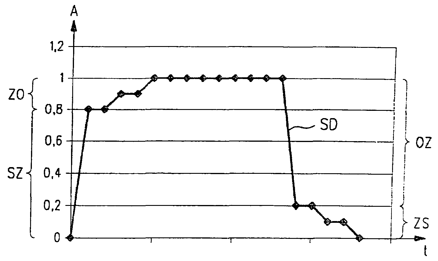
[0019]Trigger signal SA shown in FIG. 1 is utilized in an internal combustion engine (not shown) to trigger a piezoelectric actuator, which adjusts a valve needle of an injection valve of the internal combustion engine from a closing position via an intermediate position to an opening position and back.

[0020]In the diagram of FIG. 1, t denotes the time axis and A a value of trigger signal SA standardized to the maximum value of trigger signal SA. Trigger signal SA is an analog signal.

[0021]For the further elucidation of the method according to the present invention, a plurality of regions SZ, Z0, 0Z, ZS of trigger signal SA are marked in the diagram of FIG. 1, which are described in the following.

[0022]At the beginning of an injection, the piezoelectric actuator (not shown) is triggered by a control device of the internal combustion engine by the portion of trigger signal SA lying in region SZ in which trigger signal SA has a relatively great slope steepness. This may ensure that th...


PUM


Abstract

A method for operating an internal combustion engine in which a valve needle of a fuel injector is adjusted from a closing position via an intermediate position to an opening position and back again. The adjustment is carried out with the aid of a piezoelectric actuator to which a trigger signal is applied. To reduce the contamination danger of the fuel injector and to keep wear of the valve needle low, the trigger signal for triggering the piezoelectric actuator has a greater slope steepness during the transition of the valve needle from the closing position to the intermediate position than during the transition of the valve needle from the intermediate position to the opening position.

Description

FIELD OF THE INVENTION[0001]The present invention relates to a control device and a method for operating an internal combustion engine in which a valve needle of a fuel injector is adjusted from a closing position via an intermediate position to an opening position and back, with the aid of a piezoelectric actuator to which a trigger signal is applied.BACKGROUND INFORMATION[0002]Conventional operating methods and control devices for such a method may be disadvantageous in that, on the one hand, they may lead to an increased contamination risk of the fuel injector and, on the other hand, they may prevent a controlled closing of the fuel injector.[0003]The increased contamination risk is due to the fact that the fuel injector is in a state of a comparatively low lift of the injection needle, and thus reduced opening of the fuel injector, for a relatively long period of time. The danger that particles get jammed between the valve orifice and the valve needle and clog the valve orifice ...

Claims


Application Information

Patent Timeline
Patent Type & Authority Patents(United States)
IPC IPC(8): F02M51/00F02M51/06F02D41/20F02D41/38F02D45/00
CPCF02D41/2096F02D41/3809
Inventor VORBACH, MARCO
Owner ROBERT BOSCH GMBH
Why Eureka
Try Eureka