Audio device

a technology of audio devices and audio data, applied in the field of digital instruments, methods and signalling, can solve the problems of further limiting system functionality, limiting the range of possible system functionality, and relatively low fidelity of sound or voice audio data

Active Publication Date: 2008-05-20
CIRRUS LOGIC INC
View PDF12 Cites 26 Cited by
  • Summary
  • Abstract
  • Description
  • Claims
  • Application Information

AI Technical Summary

Benefits of technology

[0010]By providing a digital audio bus architecture with unitary and divided or dual modes of operation the embodiment reduces the number of buses required and therefore allows further miniaturisation of an audio convergence device supporting two or more types of audio, for example “lo-fi” telephony voice and hi-fi music.
[0012]This allows simultaneous transmissions of two audio data communications on different bus sections, or a single transmission on both sections. This in turn allows for a greater flexibility and number of audio based applications for audio convergence devices.
[0015]The pass device may be a passive device such as a resistor; which is cheap to implement. Alternatively it may be implemented by an active circuit for example utilising a switchable unidirectional buffer which provides greater isolation between the bus sections in the split mode of operation and may allow for a faster data rate on the bus in the unitary mode.
[0020]In an embodiment a sub-circuit coupled to the first bus section and a sub-circuit coupled to the second bus section each have a buffer for coupling to the bus. Each buffer receives an input signal and has driving circuitry arranged to drive the bus to a voltage level dependent on the input signal. Each buffer also receives an independent enable or disable signal which prevents the buffer driving the bus, i.e. it places the buffer into a high-impedance or tri-state mode. This arrangement can be used to avoid contention on the bus when a resistor is used as the pass device.
[0034]In one aspect there is provided an audio codec for converting digital audio signals to analogue audio signals, the audio codec comprising two digital audio bus interfaces for coupling to respective digital audio buses and a digital-only signal path between the two digital audio bus interfaces, such that no analogue processing of the audio signals occurs in the digital-only signal path. In its simplest form, where the two digital audio bus interfaces use the same sample rate and digital format, the digital audio data can be simply transferred from one interface to the other. Some simple manipulation and retiming of the signal may be employed for example involving some temporary signal storage such as a FIFO. The digital only signal path may also comprise a digital format conversion function where the two digital audio bus interfaces use different digital formats, for example PCM and AC. This may involve repeating or omitting samples if the input and output data rates are different. Some embodiments may comprise digital signal processing, for example volume control, digital filtering, or mixing of other signals, or sample-rate-conversion, involving digital addition and multiplication of the signals.

Problems solved by technology

However the need for sharing the bus can preclude certain modes of communication and hence limit the range of possible system functionality.
However the fidelity of the sound or voice audio data is relatively low, typically a single or mono 8 kHz channel.
Both are complex systems in their own right, and operate with largely different interfaces and protocols, so are designed largely independently, even if integrated on a common substrate.
A problem with this approach however is that because of cost, size and power constraints, the two sides (communications and applications) of the device must share the audio transducer resources, for example external speaker and headphones.
However this makes further demands on the shared audio data bus which can further limit system functionality.

Method used


Image

  • Audio device
  • Audio device
  • Audio device

Examples


Embodiment Construction

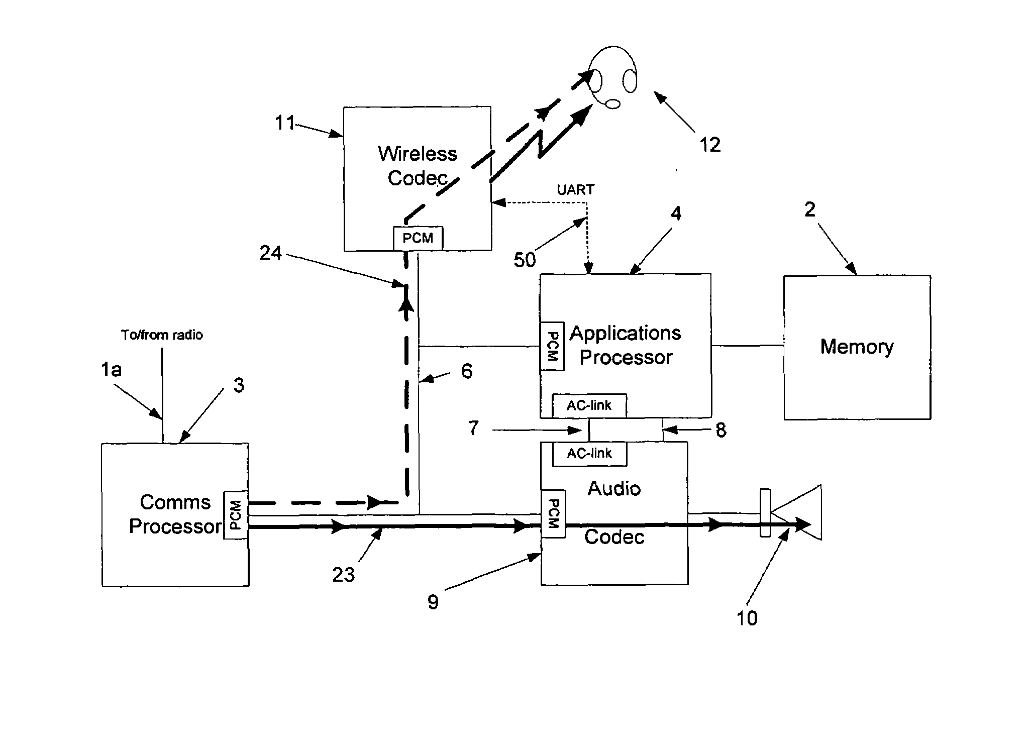
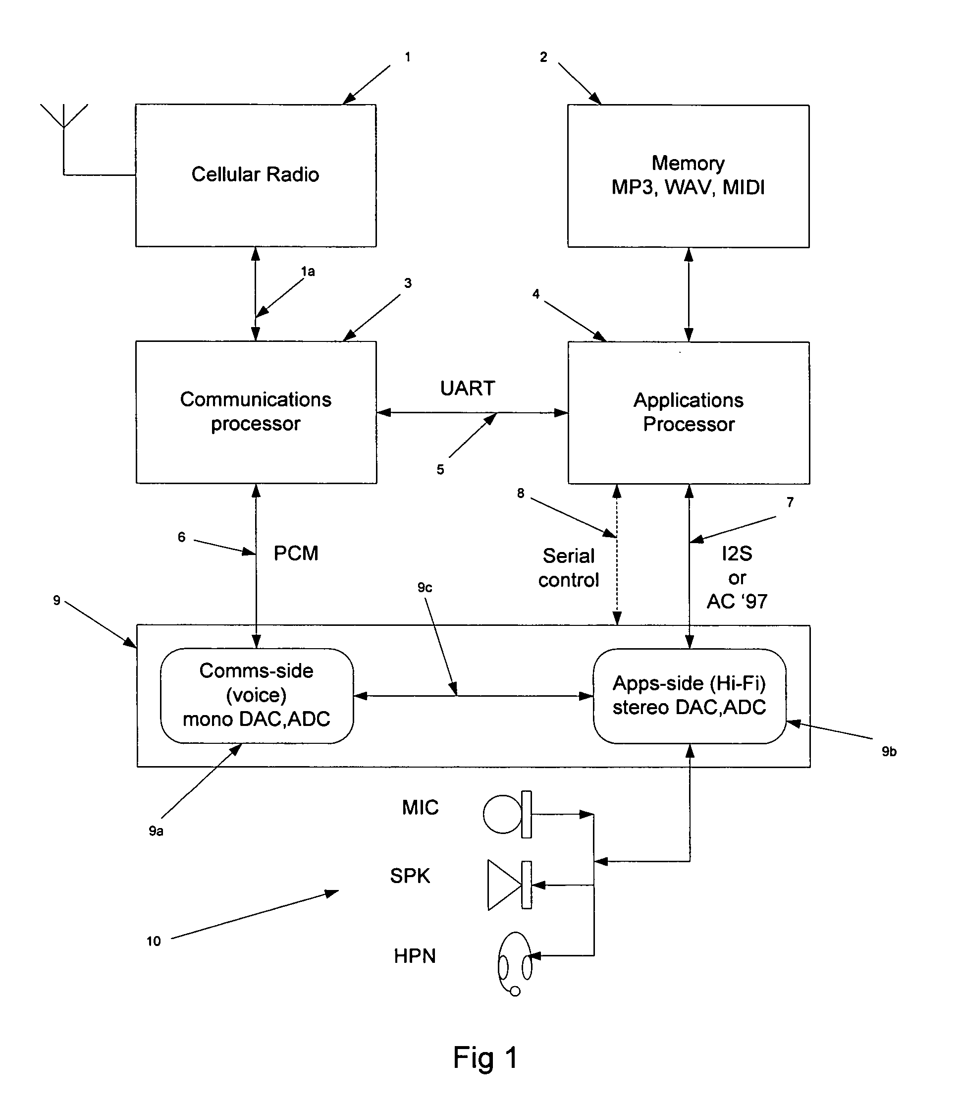
[0080]Referring to FIG. 1, the audio based architecture of an audio convergence device such as a Smartphone is shown and comprises a cellular radio 1 such as a GSM transceiver; a memory 2 for storing audio files such as MP3, MIDI, and WAV (or any program code used to run the platform); a communications processor 3 such as a specialised DSP; an applications processor 4 such as a general purpose CPU; a dual audio codec 9; various audio transducers shown generally as 10 and including a microphone, a speaker, and headphones; buses 5, 6, 7, and 8 between the communications and applications processors 3 and 4 and the codec 9.

[0081]The type or format of the buses (5, 6, 7, 8) or connections between the circuits will depend on their function and the types of data to be transferred as known, and will typically include: a serial connection 5 such as a UART bus between the communications and applications processors 3 and 4; a PCM or pulse coded modulation bus 6 between the communications proce...


PUM


Abstract

The present invention provides a digital bus circuit comprising: a bus conductor having two sections each connected to a pass circuit, each bus section being connected to two bus interfaces for respective circuits; at least three of the bus interfaces comprising a tri-state output buffer having a tri-state mode and one or more logic output modes; wherein in a unitary bus mode the tri-state output buffers are arranged such that only one of said output buffers is not in a tri-state mode, and the pass circuit is arranged to substantially couple said bus sections; and wherein in a dual bus mode the tri-state output buffers are arranged such that only one of the output buffers connected to each bus section is not in a tri-state mode, and wherein the pass circuit is arranged to substantially isolate said bus sections.

Description

FIELD OF THE INVENTION[0001]The present invention relates to digital apparatus, methods and signalling for enabling communications between a number of inter-connected circuits, and is especially though not exclusively related to digital audio communications in a digital audio convergence device such as a Smartphone.BACKGROUND OF THE INVENTION[0002]A bus is a shared communications path comprising a number of conductors connected to a number of devices, chips or circuits for example chips on an integrated circuit board. By using a contention protocol, a sub-set of the circuits can use the bus for their own communications purposes for a period of time. A bus therefore reduces the number of conductors needed to provide communications between a number of inter-connected circuits which is highly valued in IC and other small scale technologies, resulting in reduced size and cost. However the need for sharing the bus can preclude certain modes of communication and hence limit the range of p...

Claims


Application Information

Patent Timeline
Patent Type & Authority Patents(United States)
IPC IPC(8): G06F13/36
CPCG06F13/4022G06F13/4004H04L25/026H04M1/6066H04M1/72442
Inventor SINAI, DAVID
Owner CIRRUS LOGIC INC
Why Eureka
Try Eureka