
Apparatus and method for spectrally shaping a reference clock signal

a technology of reference clock signal and spectrally shaping method, which is applied in the direction of digital-analog converters, automatic control, instruments, etc., can solve the problems of noise being injected into the feedback signal, particularly sensitive to clock signal jitter, and source of error in converters

Active Publication Date: 2008-05-27
INTEL GERMANY GMBH & CO KG
View PDF7 Cites 16 Cited by
  • Summary
  • Abstract
  • Description
  • Claims
  • Application Information

AI Technical Summary

Benefits of technology

"The invention provides an apparatus and method for spectrally shaping a reference clock signal for a converter. This involves detecting clock signal jitter in the reference clock signal and modulating the pulse widths of clock pulses in the reference clock signal based on the detected jitter. The technical effect is to improve the stability and accuracy of the reference clock signal, which can enhance the performance and reliability of the converter."

Problems solved by technology

Clock signal jitters are a source of error in converters, particularly in clocked digital-analogue converters.
A drawback of sigma-delta analogue-digital converters based on the prior art is that they are particularly sensitive towards clock signal jitters.
If the reference clock signal which clocks the digital-analogue converter DAC fluctuates over time, this clock signal jitter results in noise being injected into the feedback signal.
However, digital-analogue converters which are produced using switched-capacitor technology have the drawback that they are relatively slow, since the charge reversal operations take a relatively long time.
Although current-controlled digital-analogue converters which produce current pulses whose amplitude is proportional to a digital value operate relatively quickly, they are sensitive towards clock signal jitters.

Method used


Image

  • Apparatus and method for spectrally shaping a reference clock signal
  • Apparatus and method for spectrally shaping a reference clock signal
  • Apparatus and method for spectrally shaping a reference clock signal

Examples


Embodiment Construction

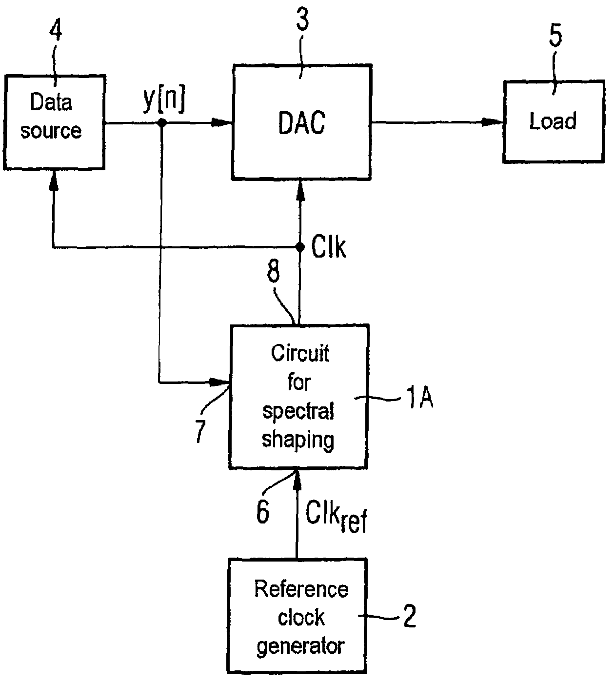
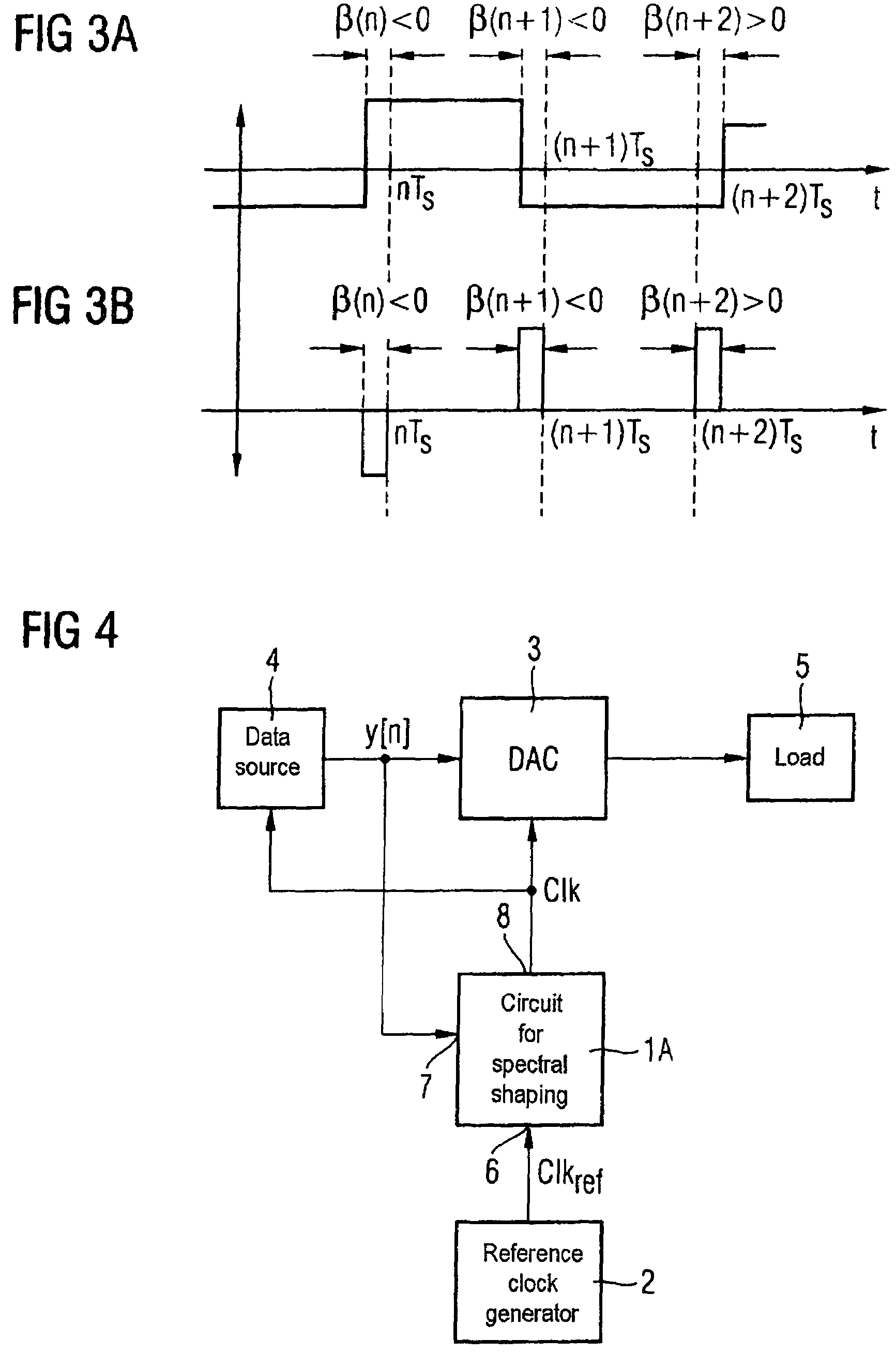
[0037]As can be seen from FIG. 4, the inventive circuit or apparatus 1 for spectral shaping is connected between a reference clock generator 2 and a digital-analogue converter 3. The reference clock signal generator 2 generates a reference clock signal CLKref which has a clock signal jitter. The reference clock signal generator 2 is any desired clock signal generator. The inventive apparatus 1 performs spectral shaping of the reference clock signal CLKref and outputs an accordingly spectrally shaped clock signal CLK to a clock signal input of the digital-analogue converter 3. The digital-analogue converter 3, which is clocked with the spectrally shaped reference clock signal, converts a digital input signal coming from a data source 4 into an analogue output signal which is output to any desired data sink or load 5. The apparatus 1 receives a digital input signal y. The apparatus 1 receives the reference clock signal at a signal input 6 and outputs the spectrally shaped reference cl...


PUM


Abstract

Clock signal jitter detection circuit for detecting a clock signal jitter in a reference clock signal (CLK), having a switched-capacitor reference digital-analogue converter (15) which is clocked by the reference clock signal (CLK) and which converts a digital input signal into a first current, a current-controlled digital-analogue converter (16) which is clocked by the reference clock signal (CLK) and which converts the digital input signal into a second current, and having a current integrator (18) which integrates the difference between the first current and the second current to produce a signal which indicates the clock signal jitter in the reference clock signal (CLK).

Description

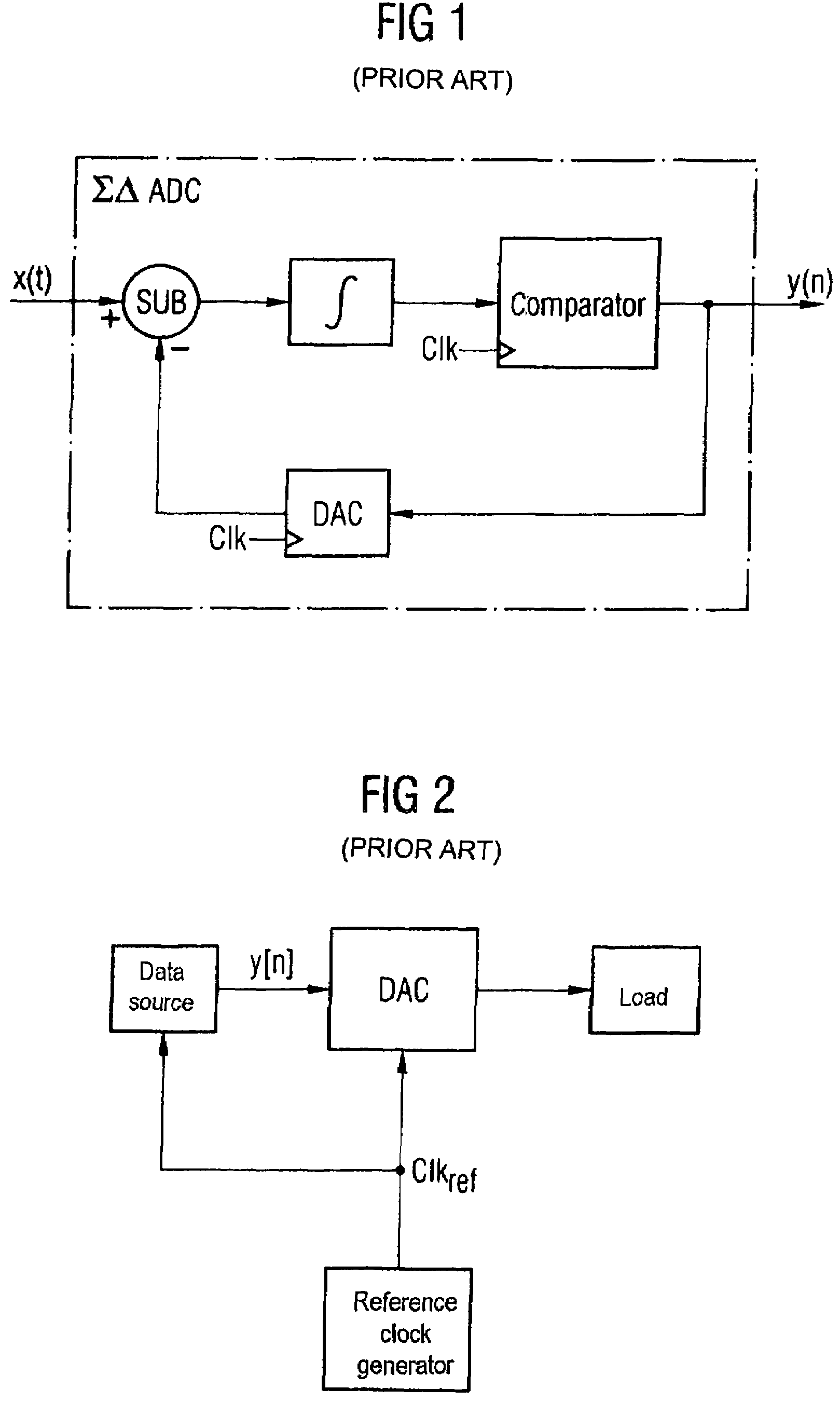
BACKGROUND OF THE INVENTION[0001]The invention relates to an apparatus and a method for spectrally shaping a reference clock signal for a converter, particularly for a digital-analogue converter, which is provided in the feedback loop of a sigma-delta modulator.[0002]Clock signal jitters are a source of error in converters, particularly in clocked digital-analogue converters. Digital-analogue converters may, inter alia, also be used in feedback loops in sigma-delta analogue-digital converters.[0003]FIG. 1 shows a block diagram of a sigma-delta analogue-digital converter based on the prior art. The analogue-digital converter ADC converts an analogue input signal into digital data or into a digital data stream. These data are then processed further and stored. The analogue-digital converter quantizes the continuous analogue input signal both in terms of time and in terms of amplitude. The digital output signal is stepped following the conversion. In the case of a sigma-delta analogue-...

Claims


Application Information

Patent Timeline
Patent Type & Authority Patents(United States)
IPC IPC(8): H03M1/66
CPCH03L7/08H03L7/18H03M3/372H03M3/464
Inventor WIESBAUER, ANDREASHERNANDEZ, LUISSTRAUSSNIGG, DIETMARGRUBER, DANIELGAGGL, RICHARDCLARA, MARTINMATSCHITSCH, STEFAN
Owner INTEL GERMANY GMBH & CO KG
Learn More