Device and process for coding video images by motion compensation
- Summary
- Abstract
- Description
- Claims
- Application Information
AI Technical Summary
Benefits of technology
Problems solved by technology
Method used
Image


Examples
Embodiment Construction
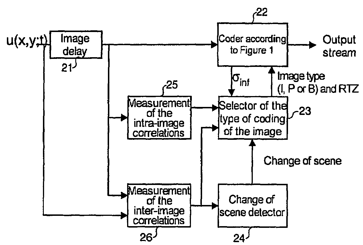
[0070]FIG. 1 represents the principle of a motion compensation coder 22 incorporating a recursive filtering device.
[0071]The following notation is used:[0072]x, y and t respectively denote the abscissa, ordinate and time,[0073]u(x,y;t): denotes a current input signal,[0074]u(x,y;t−T): denotes an input signal retarded by a delay T (T represents a delay of one video frame for example),[0075]D(dx,dy): denotes a displacement vector, dx designating the offset (shift) in displacement along the abscissa axis and dy the offset in displacement along the ordinate axis,[0076]v(x,y;t) denotes the output of the filter,[0077]v(x+dx,y+dy;t−T) denotes the motion-compensated output from the filter, retarded by a delay T,[0078]α: denotes the recursivity coefficient for the current sample,[0079]σinf: denotes the lower limit of an estimated noise level for the whole image,[0080]σsup: denotes the upper limit of an estimated noise level for the whole image,[0081]NL: denotes a non-linear function α=f(ε,σi...
PUM
 Abstract
Description
Claims
Application Information