
Method of coating a ceramic matrix composite fiber

a ceramic matrix and composite fiber technology, applied in the field of ceramic matrix composite fiber coating, can solve problems such as difficulties, and achieve the effect of improving the uniform coating of cmc fibers

Inactive Publication Date: 2008-06-03
GENERAL ELECTRIC CO
View PDF20 Cites 9 Cited by
  • Summary
  • Abstract
  • Description
  • Claims
  • Application Information

AI Technical Summary

Benefits of technology

[0007]The invention provides a method and reactor that improves the uniform coating of CMC fibers. According to the invention, a method of coating a CMC fiber comprises passing the fiber through a reactor zone along a path substantially parallel to a

Problems solved by technology

While this is possible when the fibers are individual filaments, it is very difficult to achieve when the fibers are collected into tows and woven, braided or knitted into fabrics.

Method used


Image

  • Method of coating a ceramic matrix composite fiber
  • Method of coating a ceramic matrix composite fiber
  • Method of coating a ceramic matrix composite fiber

Examples


examples

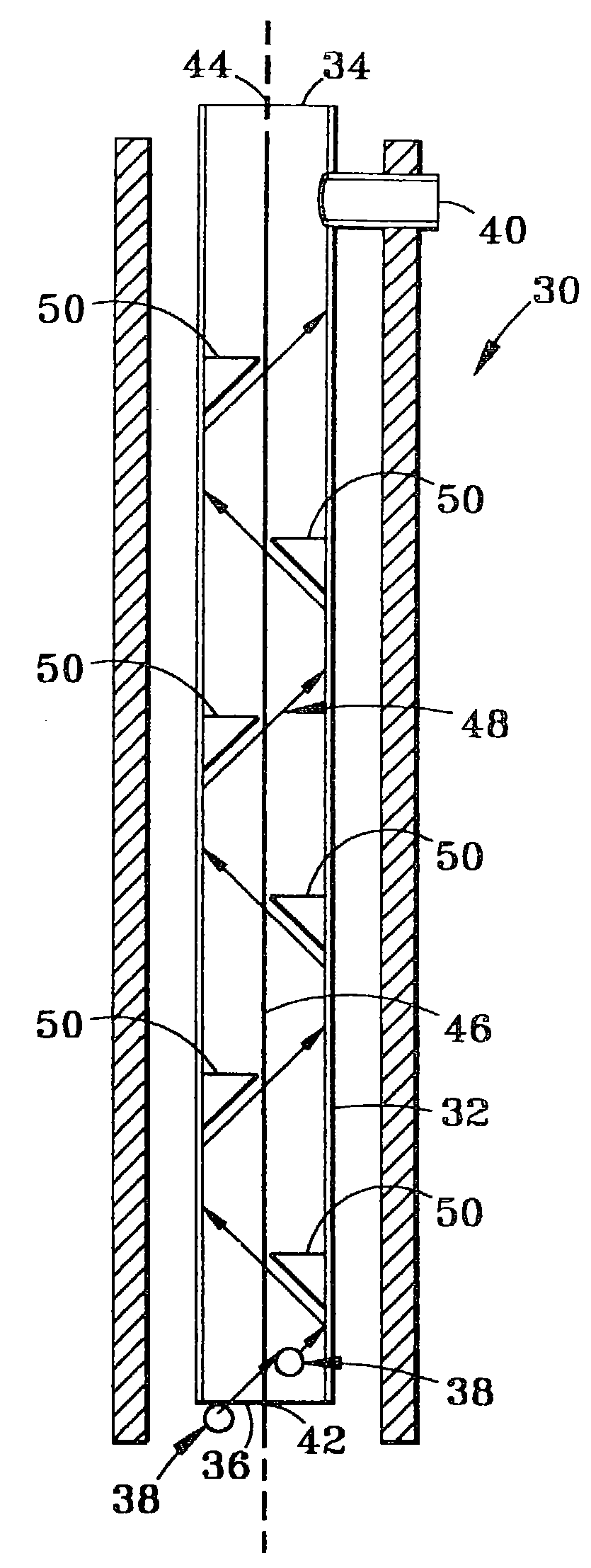
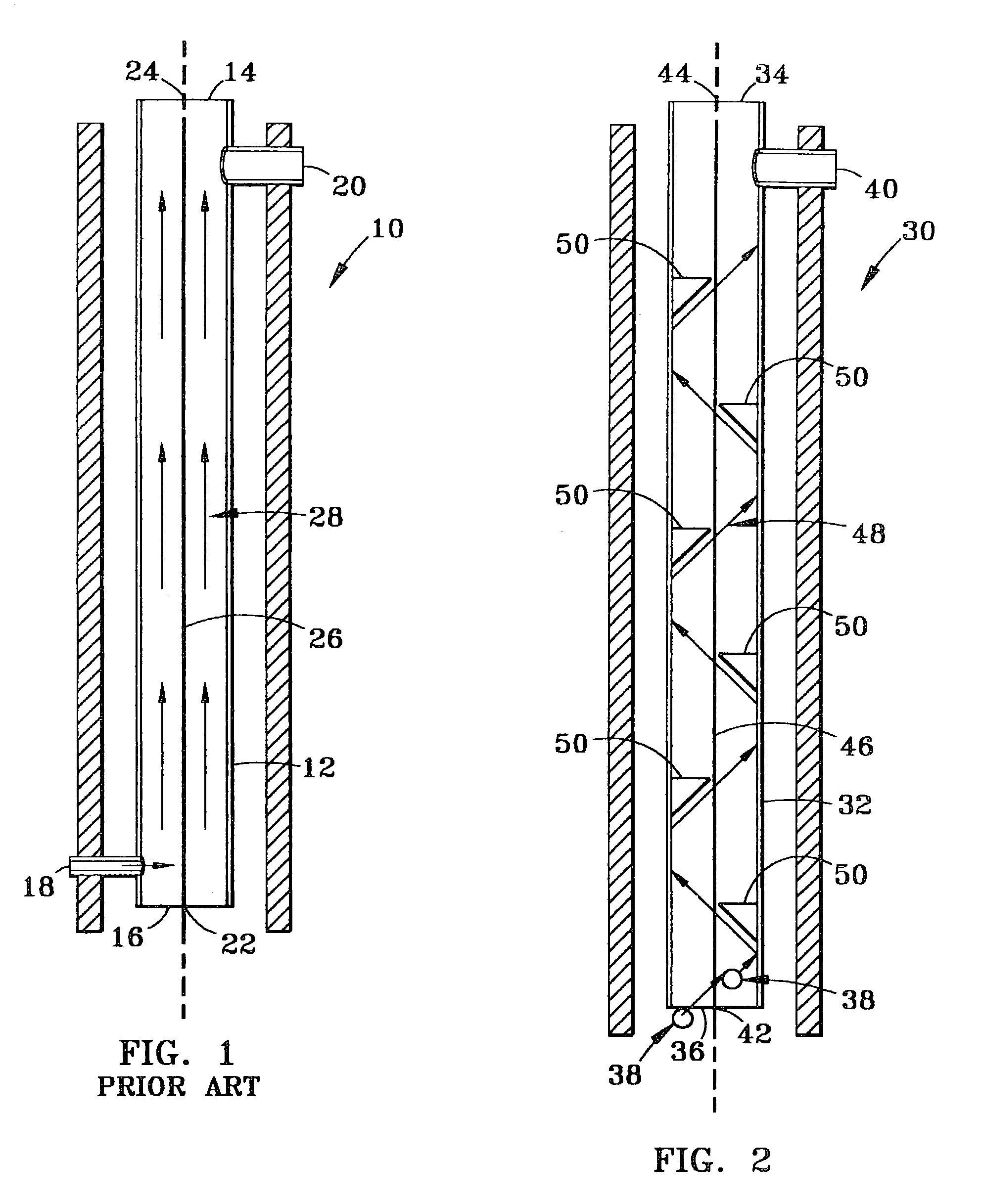
[0044]Several bundles of Nicalon, a silicon carbide fiber from Nippon Carbon Company, were wound on a spool and installed into a spool box on one end of a CVD reactor. The fibers were passed through the CVD reactor as an array of bundles and were attached to a pick up spool in a receiving box on the opposite end of CVD reactor. End boxes were connected to the reactor chamber by narrow slits, just large enough to pass the fiber bundle. The deposition chamber was a graphite tube of uniform cross section, with flow disrupters installed along its length. The chamber had a total of six disrupters in the form of ⅝-inch long wedges attached alternately to opposite sides of the chamber wall as shown in FIG. 2.

[0045]The reactor was evacuated and a flow of nitrogen gas was introduced into the reactor chamber through each end box as a seal against reactant leakage. The reactor chamber was heated to 1450° C. Reactant gases, boron trichloride and ammonia, were injected into the bottom of the rea...


PUM

PropertyMeasurementUnit
Temperatureaaaaaaaaaa
Lengthaaaaaaaaaa

Abstract

A method of coating a ceramic matrix composite fiber is disclosed. The method includes passing the composite fiber through a reaction zone along a path substantially parallel to a longitudinal axis of the reaction zone. It also includes passing a flow of a fiber coating reactant through the reaction zone. Further, the method includes disrupting a portion of the flow of the fiber coating reactant from a path substantially parallel to a fiber path to create a mixing flow adjacent the composite fiber.

Description

[0001]This is a divisional of application Ser. No. 09 / 728,904 filed Dec. 4, 2000, now U.S. Pat. No. 6,630,029.BACKGROUND OF THE INVENTION[0002]The invention relates to a method and reactor for applying a coating to a fiber by chemical vapor deposition (CVD).[0003]Fiber reinforced ceramic matrix composites (CMCs) are formed of continuous uniaxial or woven fibers of ceramic material embedded in a ceramic matrix. These materials are designed to have a weak fiber-matrix bond strength. When a CMC is loaded above a stress that initiates cracks in the matrix, the fibers debond from the matrix allowing fiber / matrix sliding without fiber fracture. The fibers bridge the matrix crack and transfer load to the surrounding matrix by transferring tensile stress to frictional interfacial shear force.[0004]Conventional manufacturing processes for CMCs have comprised, first, preparing a flowable suspension of the ceramic matrix material in powdered form, coating or immersing the inorganic fibers (usu...

Claims


Application Information

Patent Timeline
IPC IPC(8): C23C16/00C23C16/44C23C16/455C23C16/54
CPCC23C16/455C23C16/45591C23C16/545C04B35/80C04B35/62884C04B2235/5244C04B2235/5224C04B35/62868C04B35/62897C04B35/00
Inventor BRUN, MILIVOJ KONSTANTIN
Owner GENERAL ELECTRIC CO
Learn More