
Intracranial stent and method of use

a technology of intracranial stents and stents, which is applied in the field of disease-causing stent delivery systems, can solve the problems of unsuitable for use in smaller blood vessels, unsuitable for critical vessels in the brain and small diameter vessels, and unsuitable for small blood vessels. , to achieve the effect of non-deformation of radial flexibility, low profile, and convenient insertion and tracking

Inactive Publication Date: 2008-06-10
MICRO THEREPEUTICS INC
View PDF33 Cites 37 Cited by
  • Summary
  • Abstract
  • Description
  • Claims
  • Application Information

AI Technical Summary

Benefits of technology

"The patent describes a stent for use in the intra-cranial blood vessels that is suitable for self-expanding or balloon-expanding stents. The stent is designed to be easily inserted and non-deforming during placement, with a low profile release mechanism that allows for easy and safe deployment without occluding the vessel. The stent can be used as a temporary or permanent device for the treatment of intra-cranial vascular disease, such as an aneurysm or rupture of a blood vessel. The delivery system includes a proximal control mechanism and distal retaining and release mechanisms, which provide for smooth and safe deployment of the stent. The stent is designed to be non-sliding and non-deforming during placement, which makes it easier to use and reduces the risk of complications."

Problems solved by technology

Occlusion of the coronary arteries, for example, is a common cause of heart attack.
The mass and size of the tumor can cause a stroke or the symptoms of stroke, requiring surgery for removal of the tumor or other remedial intervention.
These stent-grafts are designed for use in the large blood vessels, and the various layers of stents and grafts make them unsuitable for use in smaller blood vessels.
Of similar construction are the single layer rolled stents such as Kreamer, Intraluminal Graft, U.S. Pat. No. Re. 4,740,207 (Apr. 26, 1988) and its reissue 34,327 (Jul. 27, 1993), which are expanded by balloon and include a ratchet mechanism which projects into the lumen of the stent, thus making it unsuitable for critical vessels in the brain and small diameter vessels.
The Szikora article and others show that knitted stents have not been effective in isolating an aneurysm from the circulatory system.
Another problem noted with this technique is that blood clots can escape the open walled stent.
This technique has reportedly resulted in clots and coils falling out of the sac, and the technique is not used on wide-neck aneurysms.
However, these techniques do not always effect an immediate and complete seal of the aneurysm from the high pressure of the circulatory system, and rupture, leakage and deadly complications occur.
Aneurysm rupture and bleeding during surgical clipping and shortly after the clip placement is a significant problem and add difficulty to the procedure.
Thus the article illustrates that GDC's do not always work, and when they fail they may leave the patient in a critical condition.
As illustrated in the article, bleeding during surgical clipping and shortly after the clip placement is also a frequent problem.
The physical characteristics of prior art balloon expandable stents and self expanding stents make them clearly unsuitable for intra-cranial use, because of their delivery profile and tendency to temporarily occlude the vessel during deployment.
Palmaz stents, Palmaz-Schatz™ stents, Wallstents, Cragg stents, Strecker stents and Gianturco stents and other stents are too rigid to allow placement in the cerebral blood vessels, some require a balloon for deployment, and all are too open to occlude an aneurysm.

Method used


Image

  • Intracranial stent and method of use
  • Intracranial stent and method of use
  • Intracranial stent and method of use

Examples


Embodiment Construction

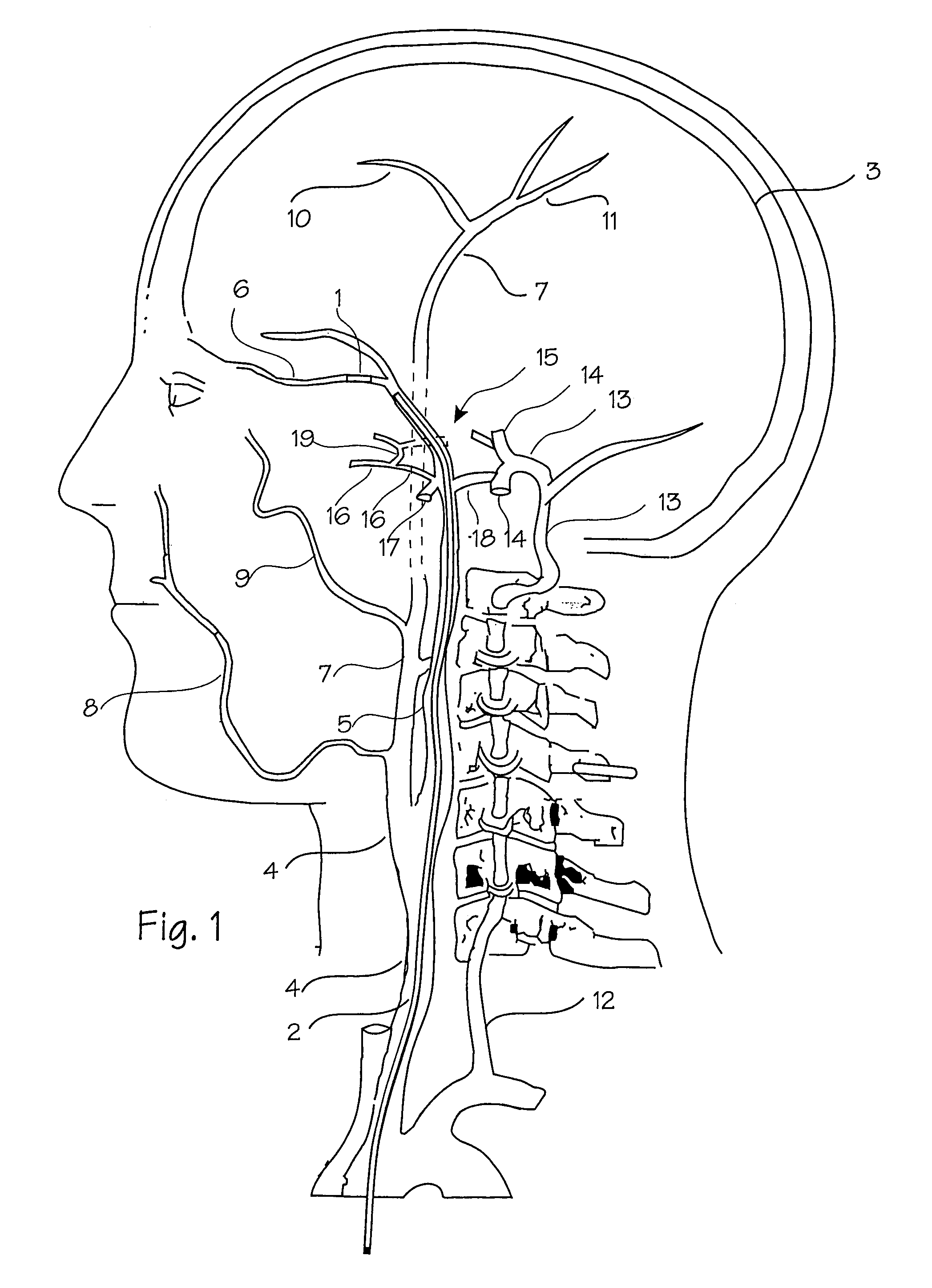
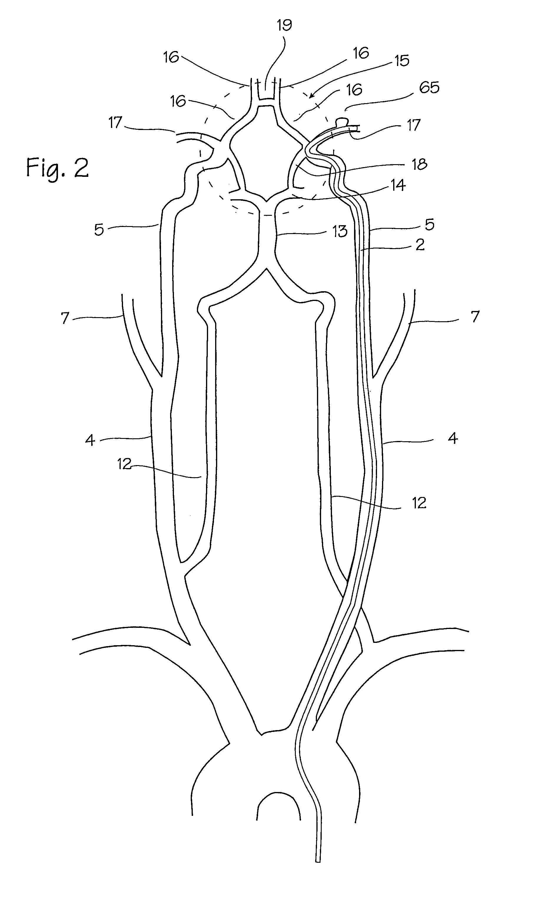
[0076]FIGS. 1 and 2 show the vasculature of the brain in sufficient detail to understand the invention. The brain 3 is supplied with blood through the carotid and the vertebral arteries on each side of the neck. The important arteries include the common carotid artery 4 in the neck, which will be the most common access pathway for the stent, the internal carotid 5 which supplies the opthalmic artery 6. The external carotid 7 supplies the maxillary artery 8, the middle meningeal artery 9, and the superficial temporal arteries 10 (frontal) and 11 (parietal). The vertebral artery 12 supplies the basilar artery 13 and the cerebral arteries including the posterior cerebral artery 14 and the circle of Willis indicated generally at 15. The siphon 12a of the vertebral artery appears in the intra-cranial vasculature on the vertebral approach to the Circle of Willis. Also supplied by the internal carotid artery are the anterior cerebral artery 16 and the middle cerebral artery 17, as well as ...


PUM


Abstract

A stent and stent catheter for intra-cranial use. The stent is a rolled sheet stent and is releasably mounted on the distal tip of the catheter by means of a non-sliding retention and release mechanism. The non-sliding release mechanism is operated remotely at the proximal end of the catheter by means of a linear translator. The stent is rolled tightly on the distal tip of the catheter and flexibility of the tightly rolled stent is promoted by ribbed or slatted construction (or, alternatively, slotted construction) in which the various layers of the stent are provided with numerous slats which counter align when the stent is expanded to form an imperforate wall from a plurality of perforate layers.

Description

[0001]This application is a continuation of U.S. patent application Ser. No. 09 / 897,218, filed Jul. 2, 2001, now U.S. Pat. No. 6,669,719, which is a continuation application of U.S. patent application Ser. No. 08 / 762,110, filed Dec. 9, 1996, now U.S. Pat. No. 6,254,628.FIELD OF THE INVENTIONS[0002]This invention relates to disease delivery systems for stents to be used to treat vascular disease.BACKGROUND OF THE INVENTIONS[0003]The inventions described below were developed with the goal of providing new and better therapies for certain types of vascular disease for which the present day therapies are widely regarded as inadequate. Vascular disease includes aneurysms which can rupture and cause hemorrhage, atherosclerosis which can cause the occlusion of the blood vessels, vascular malformation and tumors. Occlusion of the coronary arteries, for example, is a common cause of heart attack. Vessel occlusion or rupture of an aneurysm within the brain are causes of stroke. Tumors fed by ...

Claims


Application Information

Patent Timeline
Patent Type & Authority Patents(United States)
IPC IPC(8): A61F2/06A61B17/12A61B17/122A61F2/00A61F2/82A61F2/90A61F2/92
CPCA61B17/1214A61F2/92A61F2/962A61B17/12118A61B17/12022A61F2230/0095A61B17/122A61B2017/1205A61F2/90A61F2002/823A61F2002/9511A61F2002/9517A61F2250/0071A61F2250/0098A61B2017/12063A61B2017/12068A61F2210/0076A61F2/9517A61F2/97
Inventor WALLACE, GEORGELENKER, JAYBERRYMAN, THOMAS J.GREENE, ROBERT R.BRENNEMAN, RODNEY
Owner MICRO THEREPEUTICS INC
Learn More