
Re-binning method for nuclear medicine imaging devices

a nuclear medicine and imaging device technology, applied in nuclear engineering, instruments, and handling using diaphragms/collimeters, etc., can solve the problems of significant affecting resolution, simple rebinning and subsequent use of 3d-modeling with iterative methods, and inability to accurately account for the effective 3d-beam angle of collimator holes

Active Publication Date: 2008-06-10
SIEMENS MEDICAL SOLUTIONS USA INC
View PDF4 Cites 13 Cited by
  • Summary
  • Abstract
  • Description
  • Claims
  • Application Information

AI Technical Summary

Benefits of technology

[0013]The re-binning method of the present invention can be applied accurately for conversion from any collimator of a group of collimators to another collimator of the group.

Problems solved by technology

However, current rebinning methods do not account accurately for the effective 3D-beam angle of collimator holes and the effect of the Point Spread Function (PSF), which provides a measure of the amount of blurring of a single point due to non-ideal optics, as a function of the position of the hole on the collimator, i.e., PSF is not stationary for converging or diverging collimators.
which significantly impacts the resolution.
Thus, a simple rebinning and subsequent use of 3D-modelling with iterative method (e.g., OSEM-3D) will not be accurate.

Method used


Image

  • Re-binning method for nuclear medicine imaging devices
  • Re-binning method for nuclear medicine imaging devices
  • Re-binning method for nuclear medicine imaging devices

Examples


Embodiment Construction

[0023]While the present invention may be embodied in many different forms, a number of illustrative embodiments are described herein with the understanding that the present disclosure is to be considered as providing examples of the principles of the invention and such examples are not intended to limit the invention to preferred embodiments described herein and / or illustrated herein.

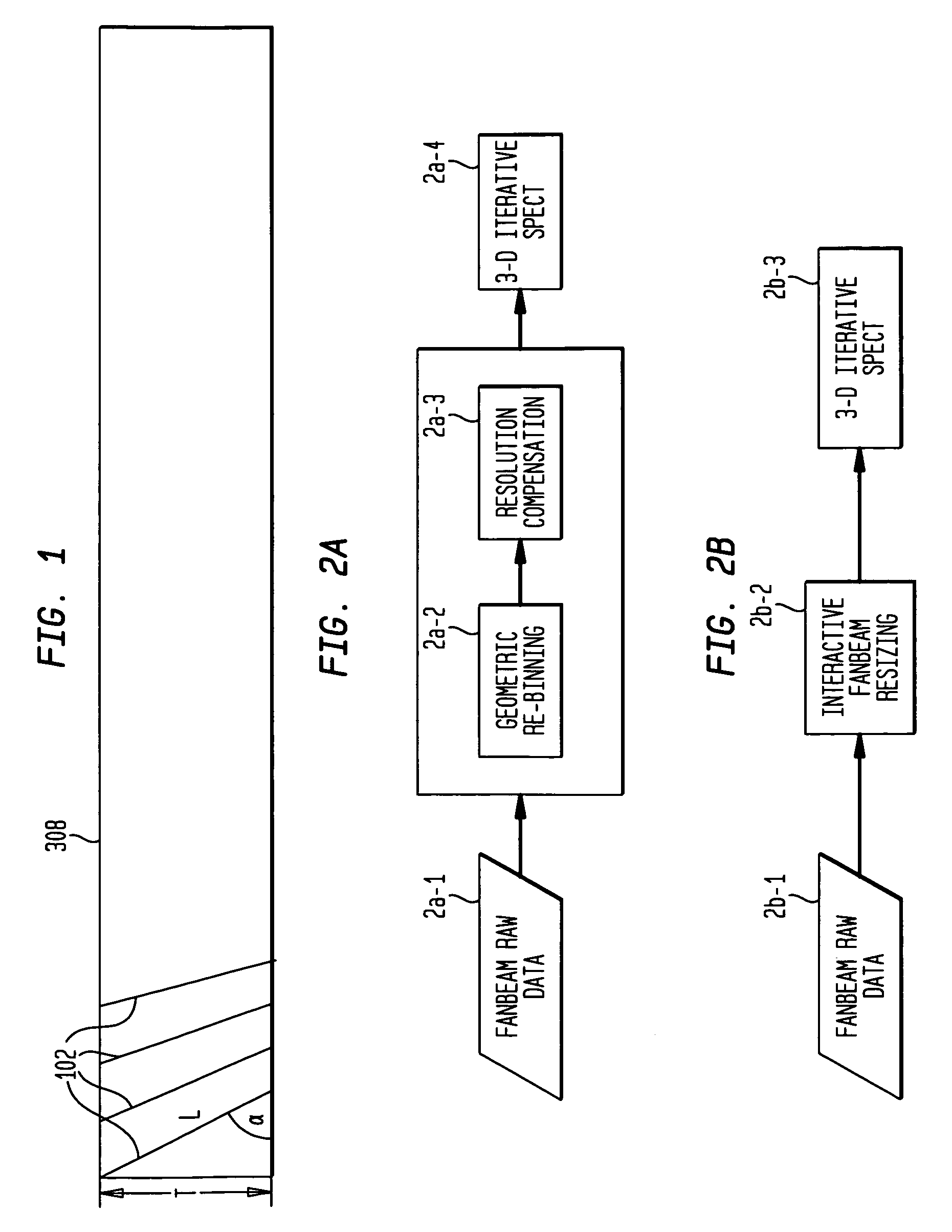
[0024]The present invention compensates for the non-stationary resolution and sensitivity issues that arise during or after the rebinning process and prepares projection data as if it had been acquired from a different, specified collimator for use in 3-D iterative SPECT reconstruction, such as 3D-OSEM. The present invention can be applied to convert data acquired with any 3-D beam converging or diverging collimator to parallel hole collimator data, or vice versa.

[0025]FIG. 2a is a flow chart of a method for performing collimator data conversion according to an embodiment of the present invention. Fanbe...


PUM


Abstract

A generalized rebinning method transforms SPECT projection data acquired with a first type of collimator into projection data as if it were acquired with a second type of collimator, for subsequent reconstruction using a 3-D algorithm devised for the second type of collimator. The method includes use of a non-stationary point-spread function in the conversion to account for image blurring.

Description

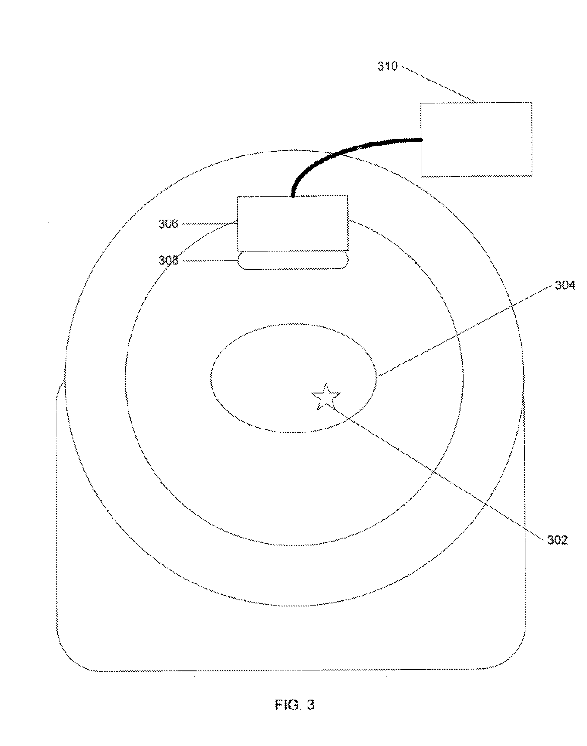
BACKGROUND OF THE INVENTION[0001]1. Field of the Invention[0002]The present invention relates generally to nuclear medical imaging devices and more particularly relates to a method for converting SPECT projection data for different collimators.[0003]2. Description of the Related Art[0004]In a nuclear medicine imaging device, such as a gamma camera for obtaining either planar images or Single Photon Emission Computed Tomography (SPECT) images, a collimator is mounted to the face of the imaging device. The collimator collimates radiation (e.g., a gamma photon) which is emitted from a source within a patient before the radiation strikes a detector crystal. In FIG. 3, a block diagram is shown of an exemplary SPECT device. A radiation source 302 within an object to be imaged 304 (e.g., human body part) emits gamma photons that emanate from the object 304 and are captured by a detector 306, which converts the detected radiation into spatial projection data. A collimator 308 collimates the...

Claims


Application Information

Patent Timeline
Patent Type & Authority Patents(United States)
IPC IPC(8): G01T1/166
CPCG06T11/005G06T2211/424Y10S378/901
Inventor VIJA, A. HANS
Owner SIEMENS MEDICAL SOLUTIONS USA INC
Learn More