
Device and method for testing machine tools and production machines

a production machine and machine tool technology, applied in the direction of programming control, instruments, computation using denominational number representation, etc., can solve the problems of significantly limiting the reproducibility of the test, difficult to conduct comprehensive tests using this conventional manual approach, and altering the test, so as to achieve convenient repeating and convenient sending

Inactive Publication Date: 2008-06-10
SIEMENS AG
View PDF9 Cites 7 Cited by
  • Summary
  • Abstract
  • Description
  • Claims
  • Application Information

AI Technical Summary

Benefits of technology

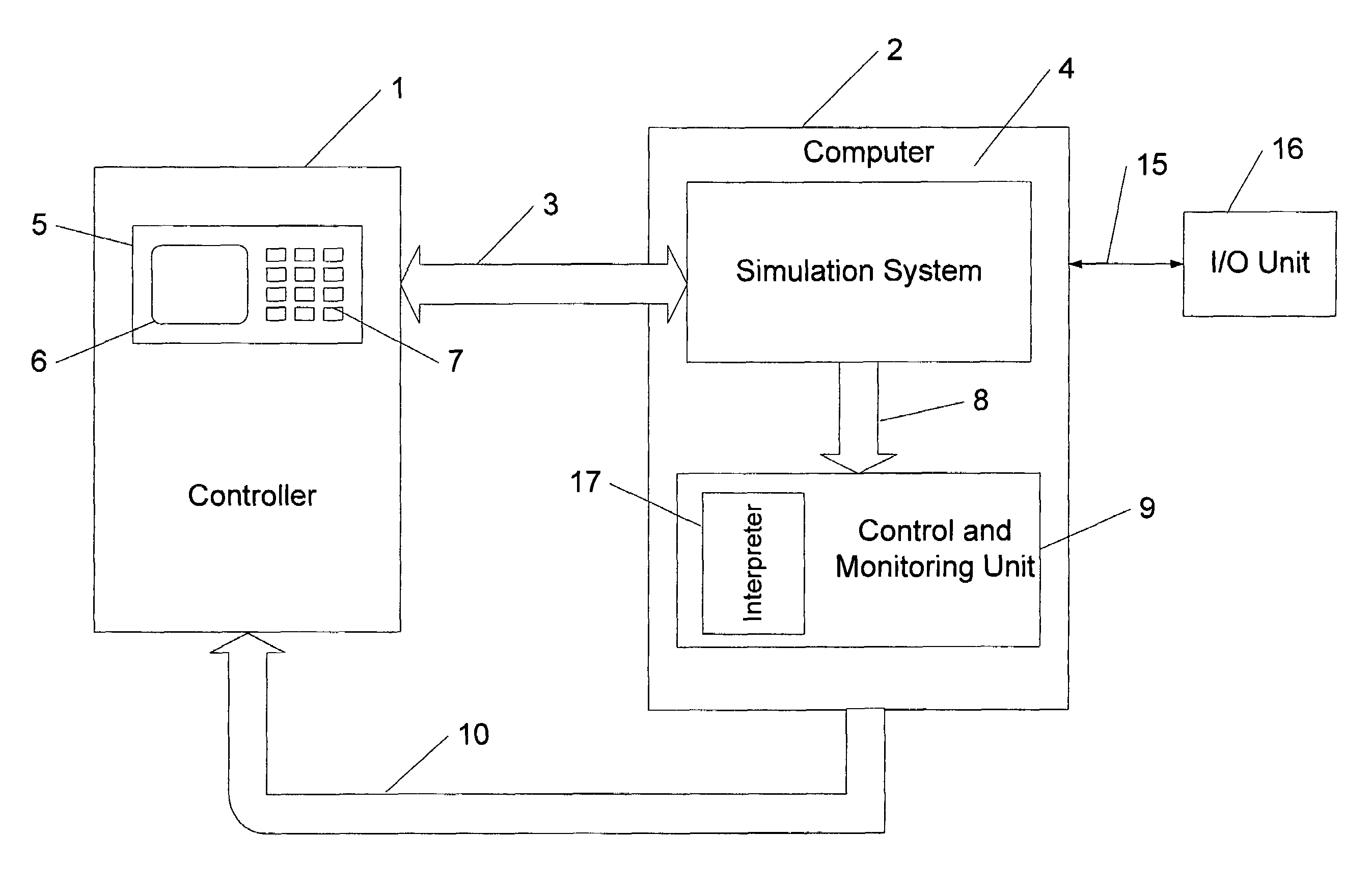
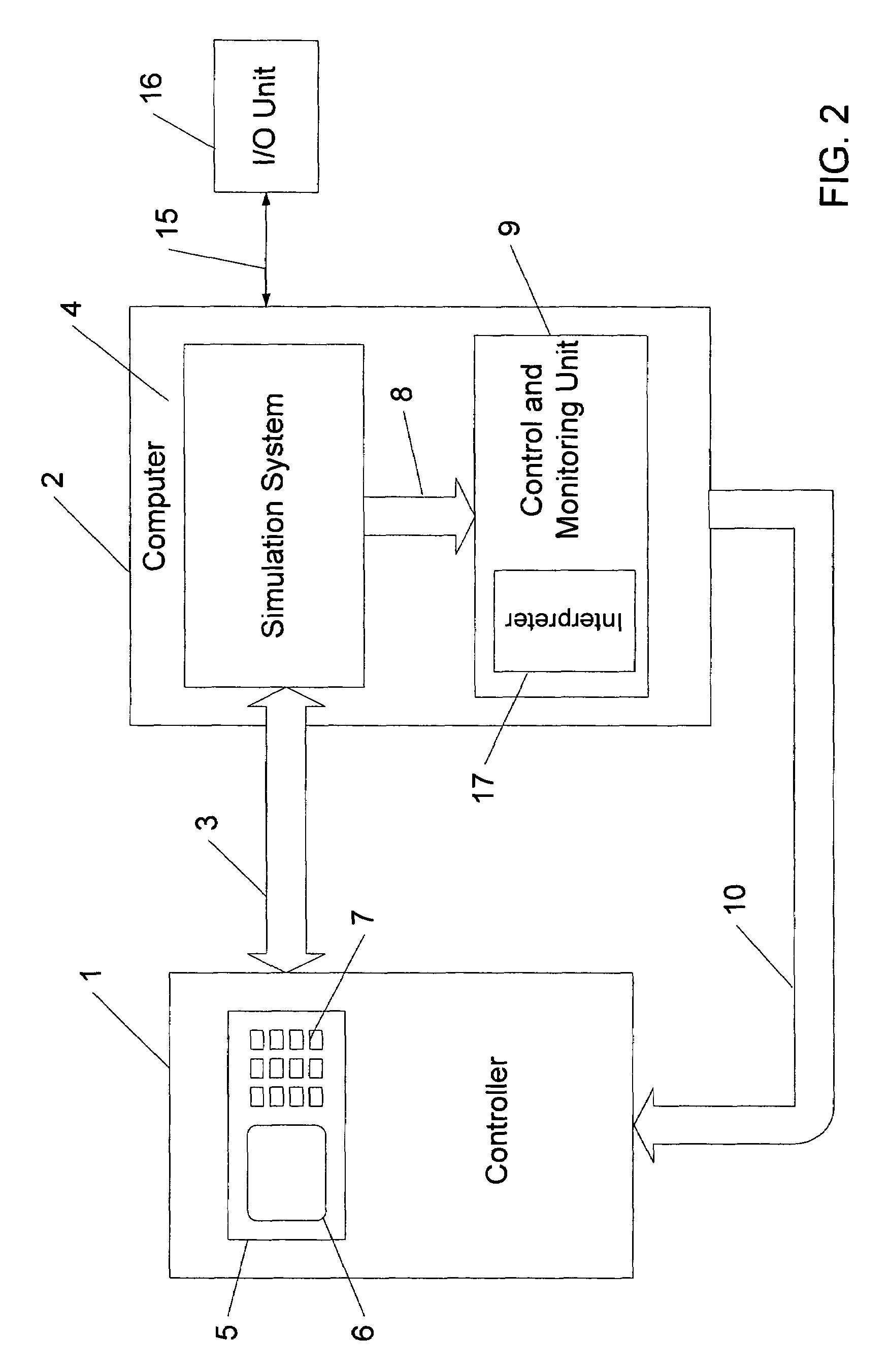
"The present invention provides a device and method for testing machine tools or production machines using a simulation system that simulates the characteristics of the machine. The device includes a simulation system, a machine controller, and an automated control and monitoring unit. The simulation system exchanges process data with the machine controller and records the process signals. The control and monitoring unit executes predefined instruction sequences and generates control commands for operating the machine controller. The instruction sequences can be programmed in a high-level language, such as Basic, and can include conditional branching, loops, value comparisons, timer functions, and I / O functions. The recorded process signals can be analyzed at a future time and the identified faults can be recorded within a trace file. The instruction sequences and trace files can be sent between customers and manufacturers of the machine controller and can be conveniently sent via the Internet. The technical effects of the invention include efficient and effective testing of machine tools or production machines without the need for physical devices and the ability to easily reproduce tests for further analysis."

Problems solved by technology

When the test is repeated, the time interval between the two operations can be shorter or longer, which can alter the test result.
It is therefore more difficult to conduct comprehensive tests using this conventional manual approach, which also significantly limits the reproducibility of the test results.

Method used


Image

  • Device and method for testing machine tools and production machines
  • Device and method for testing machine tools and production machines
  • Device and method for testing machine tools and production machines

Examples


Embodiment Construction

[0027]Throughout all the Figures, same or corresponding elements are generally indicated by same reference numerals. These depicted embodiments are to be understood as illustrative of the invention and not as limiting in any way. It should also be understood that the drawings are not necessarily to scale and that the embodiments are sometimes illustrated by graphic symbols, phantom lines, diagrammatic representations and fragmentary views. In certain instances, details which are not necessary for an understanding of the present invention or which render other details difficult to perceive may have been omitted.

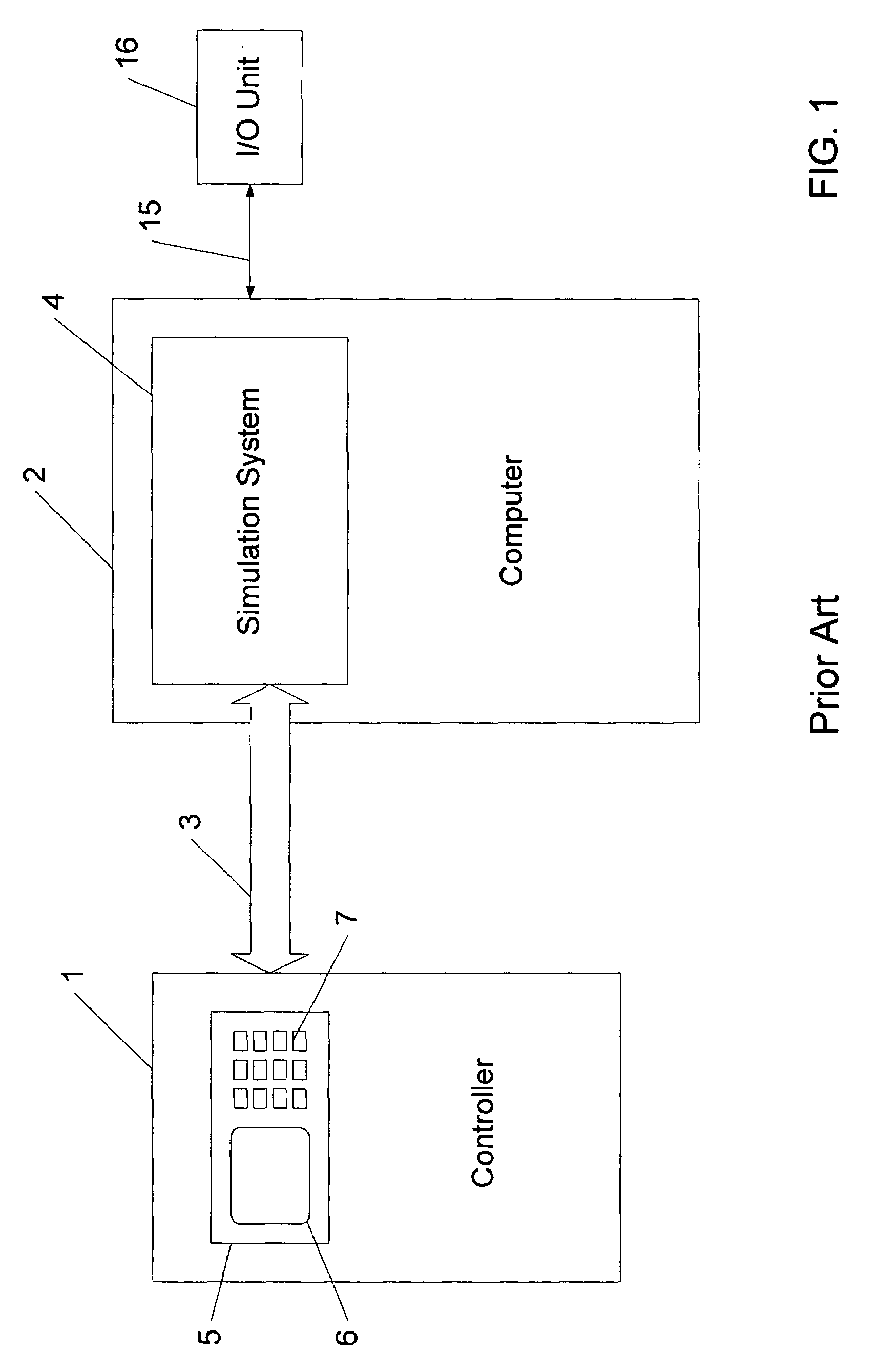
[0028]Turning now to the drawing, and in particular to FIG. 2, there is shown an exemplary embodiment of the test device of the invention. The test device of the invention depicted in FIG. 2 includes a number of basic elements that are also found in the test device depicted in FIG. 1.

[0029]As shown in FIG. 2, a controller is connected via a bus link 3 with a simulation system ...


PUM


Abstract

A test device and a test method for testing a machine tool or production machine are disclosed. A control and monitoring unit processes at least one predefined instruction sequence and generates control commands for operating the machine controller in order to test the machine. The control commands are transmitted to the machine controller, where they are executed. The instruction sequence also includes control instructions. This results in a relatively simple test device and method for automatically and reproducibly testing a machine tool or production machine.

Description

CROSS-REFERENCES TO RELATED APPLICATIONS[0001]This application claims the priority of German Patent Application, Serial No. 103 41 325.1, filed Sep. 8, 2003, pursuant to 35 U.S.C. 119(a)-(d), the disclosure of which is incorporated herein by reference.BACKGROUND OF THE INVENTION[0002]The present invention relates to a device for testing machine tools and production machines, whereby a machine controller is connected to a simulation system that simulates the characteristic of the machine for exchange of process data therebetween. The present invention is also directed to a method for testing machine tools and production machines, wherein process data are exchanged between a machine controller and a simulation system.[0003]Nothing in the following discussion of the state of the art is to be construed as an admission of prior art.[0004]The quality of system software and application software can be improved and control systems and applications for machine tools or production machines ca...

Claims


Application Information

Patent Timeline
Patent Type & Authority Patents(United States)
IPC IPC(8): G06F19/00G01M15/00G05B17/02G05B19/4069
CPCG05B19/4069
Inventor DOHLE, STEFANMENZEL, THOMAS
Owner SIEMENS AG
Learn More