Magnetic field sensor

a magnetic field sensor and sensor technology, applied in the field of magnetic field sensors, can solve the problems of large amount of effort for assembly and manufacture of conventional magnetic field sensors, carried out with very high precision, and easy to adapt to, and good anchoring

Inactive Publication Date: 2008-06-24
SIEMENS AG
View PDF11 Cites 12 Cited by
  • Summary
  • Abstract
  • Description
  • Claims
  • Application Information

AI Technical Summary

Benefits of technology

[0008]The attachment of the permanent magnet to the housing offers a number of advantages over the prior art. Since the housing is normally designed to be robust and rigid in order to protect the Hall probe, it is particularly suitable for holding the permanent magnet, which is generally heavy. In this case, it has been found to be particularly advantageous that the shape of the housing can easily be adapted to this object. One major advantage is based on the fact that the permanent magnet need no longer be attached by means of adhesive in a complex manner to a holder which was generally attached to a printed circuit board in the prior art.
[0009]Particularly good anchoring and excellent electrical and electronic characteristics of the magnetic field sensor are achieved by the permanent magnet being in the form of a ring or hollow cylinder. This means that the housing can offer an additional interlocking holder for the permanent magnet, in a particularly simple form. With regard to the alignment of the longitudinal axis of the permanent magnet in the direction of the induction axis of the Hall sensor, magnetic field sensor pulses which can be evaluated particularly well are produced in virtually all operating conditions. The induction axis is in this case defined as being oriented at right angles to the electrical field direction of the Hall voltage and to the electrical main current direction in the Hall probe. The best results are achieved when the induction axis coincides with the cylinder longitudinal axis of the permanent magnet.
[0010]The housing may be at least partially composed of plastic, which is advantageous in terms of manufacture and with regard to the EMC characteristics. Optimization with regard to the EMC characteristics is achieved in particular by the housing not forming a capacitor (which is susceptible to interference) with the Hall probe or the Hall IC. This can reliably be avoided by the housing being composed completely of plastic. For the preferred field of use of the magnetic field sensor according to the invention, it is particularly expedient for the plastic to be resistant to high temperature.
[0011]One advantageous development of the invention provides for the magnetic field sensor to have a plug or a plug socket, which is in the form of a plastic part with extrusion-coated contacts. An embodiment such as this in particular assists the modular configuration of the sensor and of the electrical lines connected to it. In addition, however, this also results in an advantageous embodiment of the magnetic field sensor according to the invention, in which the housing has a closable housing base body, and the plug socket or the plug and the housing base body can be welded to one another, provided that the housing base body is likewise manufactured from an appropriate plastic. The preferred welding methods for these two components are ultrasound welding, vibration welding or rotation welding.
[0012]According to the invention, the housing or the housing base body is preferably in the form of an injection-molded component, with the permanent magnet being sprayed into the housing. This allows an excellent connection to be produced between the permanent magnet and the housing, in just one operation. An embodiment such as this furthermore makes it possible for the housing base body to be shaped in the preferred manner as a closable sleeve-like cylinder which is closed at one end, with the Hall probe preferably being arranged in the closed end of the cylinder. This results in particularly robust protection, because of the closed end of the housing, for the Hall probe and in the permanent magnet being held in a particularly robust manner in the housing base body. Particularly if the permanent magnet is in the form of a ring or hollow cylinder, it is recommended that the Hall probe be arranged such that the induction axis extends parallel to the cylinder longitudinal axis of the housing.

Problems solved by technology

The disadvantage of the large amount of effort for assembly and manufacture of conventional magnetic field sensors is evident from the large number of work steps, only some of which have been mentioned here, but which must be carried out with very high precision.

Method used


Image

  • Magnetic field sensor
  • Magnetic field sensor

Examples


Embodiment Construction

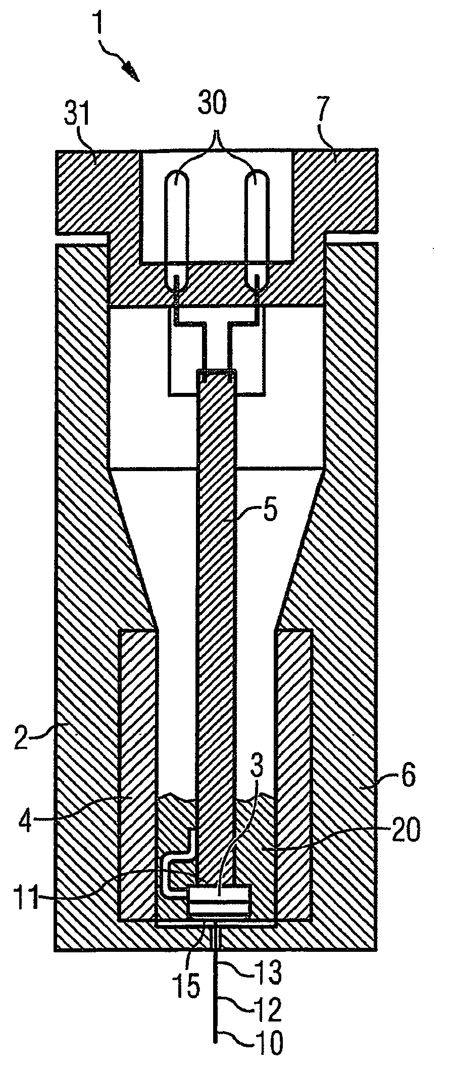
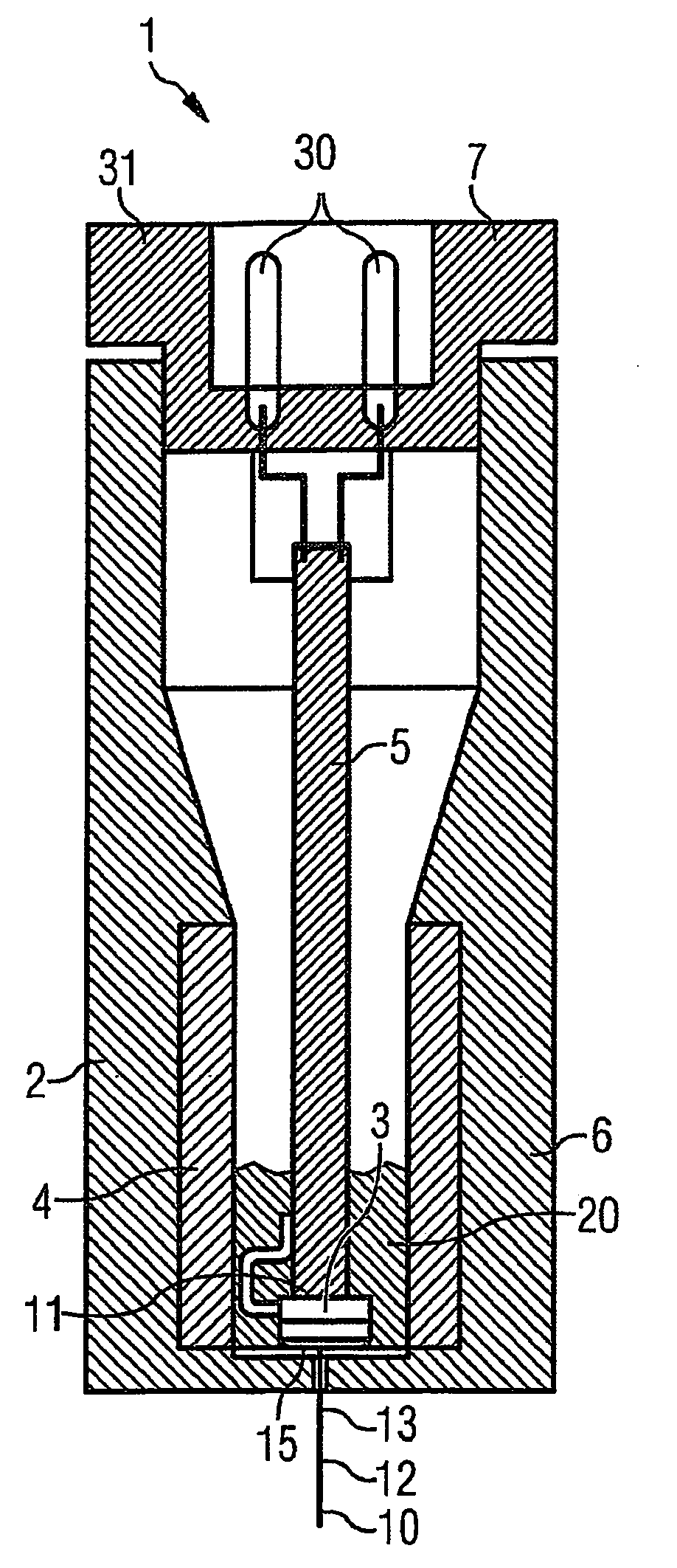
[0018]In FIG. 1, a magnetic field sensor 1 according to the invention is provided with the reference symbol 1. Major components of the magnetic field sensor 1 are a housing 2, a Hall probe 3, a permanent magnet 4, with the Hall probe 3 being attached to a printed circuit board 5.

[0019]The cylindrical housing 2 has a housing base body 6 and a molding 7, in the form of a closure. The housing 2 has a cylindrical shape, with the housing base body 6 being manufactured as an injection-molded component composed of plastic, and having a closed end 8 and an open end 9. The printed circuit board 5 extends along a cylinder longitudinal axis 10 of the housing 2. In the area of the closed end 8 of the housing 2, the permanent magnet 4, which is in the form of a hollow cylinder, is encapsulated in the housing base body 6.

[0020]The Hall probe 3, which is in the form of a Hall IC, is located on an end face 11 of the printed circuit board 5 at the closed end 8 of the housing base body 6. An inductio...


PUM


Abstract

A magnetic field sensor for measuring the rotational speed of a rotating gear component is disclosed. The sensor includes a Hall probe, at least one permanent magnet and housing. The Hall probe is arranged in the influence area of the magnetic field of the permanent magnet. The intent is to produce the magnetic field sensor in a less complex manner. This is achieved by virtue of the fact that the permanent magnet is secured to the housing. One particular advantage of the device is that it is extraordinarily robust and is only slightly sensitive to vibrations.

Description

BACKGROUND OF THE INVENTION[0001]The invention relates to a magnetic field sensor, in particular for measurement of the rotation speed of a rotating transmission component, having a Hall probe having at least one permanent magnet, with the Hall probe being located in the area of influence of the magnetic field of the permanent magnet, having a housing which surrounds the Hall probe, wherein the permanent magnet is attached to the housing, wherein the housing is at least partially composed of plastic and the permanent magnet is in the form of a ring or hollow cylinder, wherein the longitudinal axis of the permanent magnet and an induction axis of the Hall sensor essentially coincide, with the induction axis being oriented at right angles to the electrical field direction of the Hall voltage and to the electrical main current direction in the Hall probe.[0002]Magnetic field sensors of the type mentioned above are preferably used for rotation speed monitoring in goods vehicles, because...

Claims


Application Information

Patent Timeline
Patent Type & Authority Patents(United States)
IPC IPC(8): G01B7/14G01B7/30F16H59/38G01D5/14G01D11/24G01P1/02
CPCG01D5/147G01D11/245G01P1/026F16H59/38
Inventor MODEST, OTMAR
Owner SIEMENS AG
Why Eureka
Try Eureka