Object positioning method for a lithographic projection apparatus

Inactive Publication Date: 2008-07-08
ASML NETHERLANDS BV
View PDF10 Cites 20 Cited by
  • Summary
  • Abstract
  • Description
  • Claims
  • Application Information

AI Technical Summary

Benefits of technology

[0032]The measuring step can be accomplished by aligning a first mark, with a known position with respect to the object, to a second mark. Alignment can be done such that the second mark is located upon the object table (e.g. in the form of a fiducial) upon which the object is placed and has a known position relative to the required position of the object. Another possibility is that the object is located on one object table and that the second mark is located upon the other object table. Alignment can also be done such that the first mark is on the substrate and the second mark is on the mask, or the other way around. Advantageously a plurality of first marks upon the object can be aligned to a plurality of second marks. The measuring step also can be accomplished using imaging means to obtain information about the first position of the object on the table. Said imaging means can be a camera system or a CCD array, able to measure the first position of the object on the table with the required precision. The information thus obtained about the first position of the object on the table, together with information regarding the required position of the o

Problems solved by technology

Said error is a so-called beam-point error, which generally increases with increasing rotation of the table 5.
The measurement error thus caused can give an error in the super-positioning of two concurrent images exposed on successive layers on the substrate 1.
This error in the super-positioning of two concurrent images is generally called an overlay error.
However, factors such as thermal instability and mechanical play can cause a transient deviation from this parallelism, which is referred to as the beam-point error. FIG. 3b shows a beam-point error dE at a rotation dS=0.
The problem is further deteriorated in that an err

Method used


Image

  • Object positioning method for a lithographic projection apparatus
  • Object positioning method for a lithographic projection apparatus
  • Object positioning method for a lithographic projection apparatus

Examples


embodiment 1

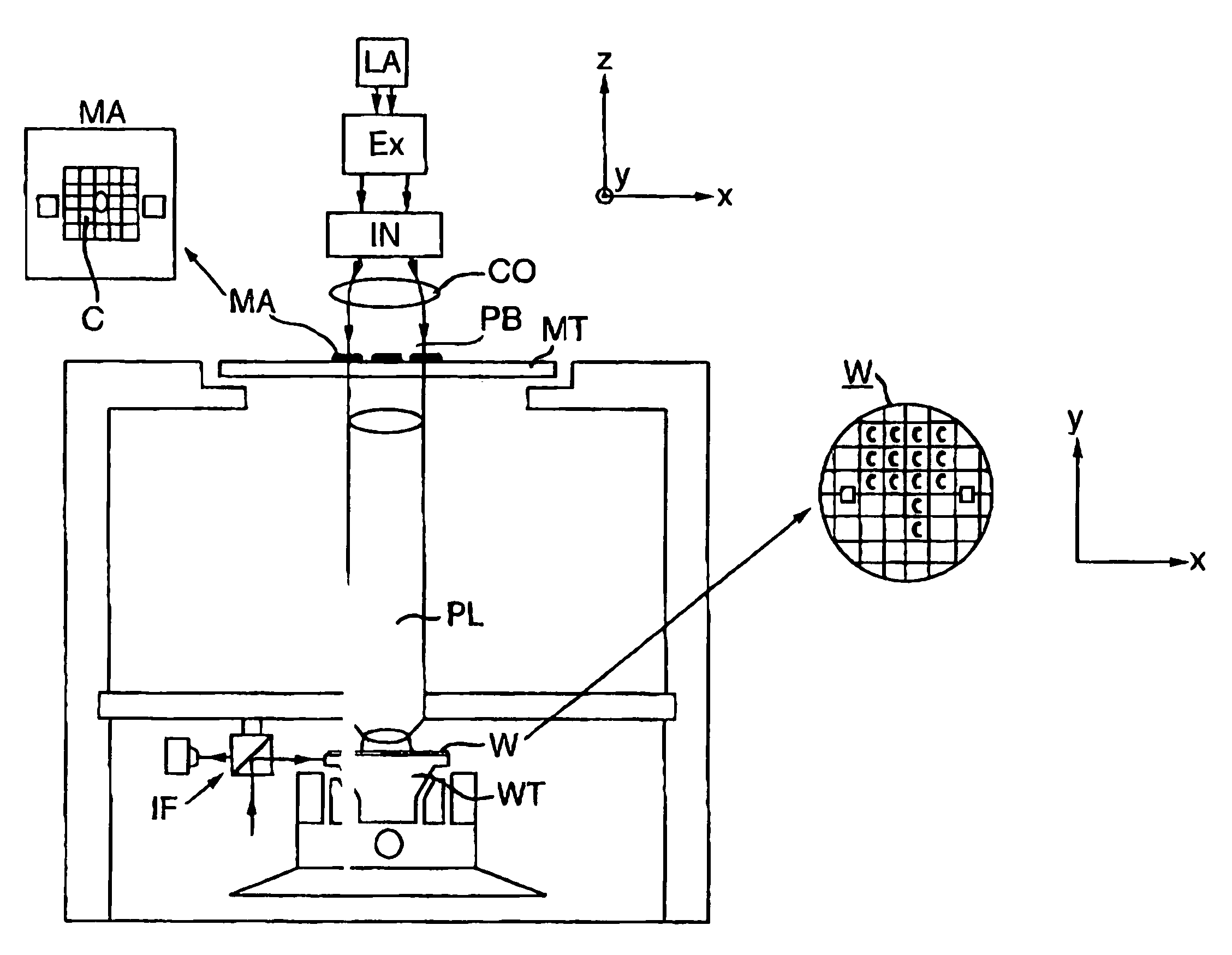
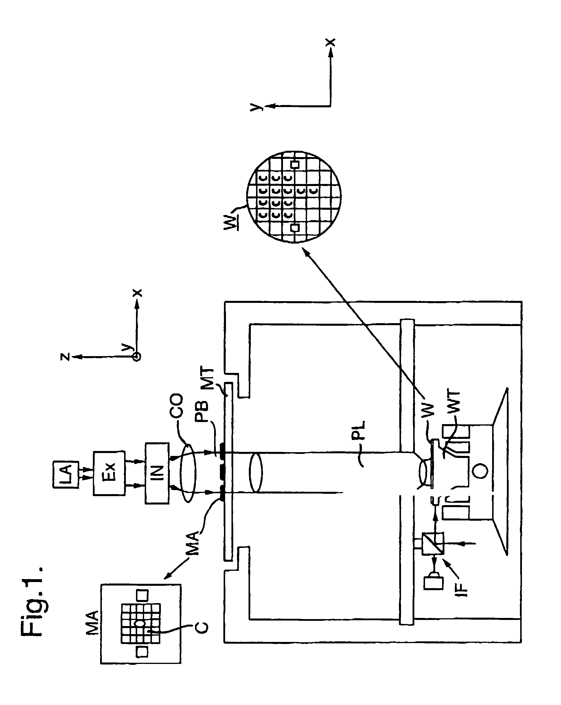
[0056]FIG. 1 schematically depicts a lithographic projection apparatus according to the invention. The apparatus comprises:[0057]a radiation system Ex, IN, CO for supplying a projection beam PB of radiation, such as ultraviolet light (e.g. at a wavelength of 365 nm, 248 nm, 193 nm or 157 nm), EUV, X-rays, electrons or ions;[0058]a first object table (mask table) MT provided with a mask holder for holding a mask MA (e.g. a reticle);[0059]a second object table (substrate table) WT provided with a substrate holder for holding a substrate W (e.g. a resist-coated silicon wafer);[0060]a projection system PL (e.g. a lens or catadioptric system, a mirror group or an array of field deflectors) for imaging an irradiated portion of the mask MA onto a target portion C (die) of the substrate W. As here depicted, the apparatus comprises refractive components. However, it may alternatively comprise one or more reflective components.

[0061]Alternatively, the apparatus may employ another kind of patt...


PUM


Abstract

A method for placement of a object such as a substrate or a mask on a table, said method including:
    • a first placement step in which the object is placed on a first position on the table;
    • a measuring step in which a displacement between the first position of the object and the required position of the object is determined;
    • a removing step in which the object is released and removed from the table;
    • a moving step in which the object and the table are moved relatively to each other by substantially the said displacement, in a direction substantially parallel to the surface of the table; and
    • a second placement step in which the object is placed at the required position on the table.

Description

[0001]The present application claims priority to European Patent Application No. 00200431.5, filed Feb. 10, 2000, which is incorporated herein by reference in its entirety.BACKGROUND OF THE INVENTION[0002]1. Field of the Invention[0003]The invention relates to a positioning method and a device, in particularly for a lithographic projection apparatus. More particular, the invention relates to a method of positioning an object such as a mask or a substrate to a required position on an object table in a lithographic projection apparatus comprising:[0004]a radiation system for supplying a projection beam of radiation;[0005]a first object table for holding patterning means capable of patterning the projection beam according to a desired pattern;[0006]a second object table for holding a substrate; and[0007]a projection system for projecting the patterned beam onto a target portion of the substrate.[0008]2. Background of the Related Art[0009]The term “patterning means” or “mask” should be ...

Claims


Application Information

Patent Timeline
IPC IPC(8): G06K9/00G03F7/22G03F7/20G03F9/00H01L21/027H01L21/68
CPCG03F9/7011G03F7/707H01L21/027
Inventor WILLEMS VAN DIJK, MARCUS J. H.VAN DE PASCH, ENGELBERTUS A. F.CASTENMILLER, THOMAS J. M.ARIENS, ANDREAS B. G.
Owner ASML NETHERLANDS BV
Why Eureka
Try Eureka