Gas sensor based on dynamic thermal conductivity and molecular velocity

a technology of molecular velocity and thermal conductivity, applied in the field of gas sensors and detection methods, can solve the problems of inability to distinguish different gas mixtures having similar thermal conductivity, limited specific gas analysis based on thermal conductivity,

Inactive Publication Date: 2008-07-15
RGT UNIV OF CALIFORNIA
View PDF11 Cites 4 Cited by
  • Summary
  • Abstract
  • Description
  • Claims
  • Application Information

AI Technical Summary

Benefits of technology

[0007]The present invention provides a device and a method for gas analysis in which three parameters—velocity, thermal conductivity and temperature—can be measured for a single gas sample. By determining three parameters in a single sample of gas, different gas mixtures having similar thermal conductivities can be distinguished, and gas mixtures having more components than binary compositions can be analyzed. In particular embodiments, the velocity, thermal conductivity and temperature of a single gas sample can be determined under high pressure and high temperature conditions. Further, the detection of hydrogen gas can be accomplished with less interference from background gases than existing hydrogen gas analyzers.

Problems solved by technology

In other thermal conductivity detector applications, specific gas analysis based on thermal conductivity has been limited to either binary gas mixtures of known gas species, or hydrogen gas in a mix of gases having similar thermal conductivities significantly different from hydrogen.
Because these methods measure only a single bulk parameter of a gas sample, different gas mixtures having similar thermal conductivities cannot be distinguished.

Method used


Image

  • Gas sensor based on dynamic thermal conductivity and molecular velocity
  • Gas sensor based on dynamic thermal conductivity and molecular velocity
  • Gas sensor based on dynamic thermal conductivity and molecular velocity

Examples


example 1

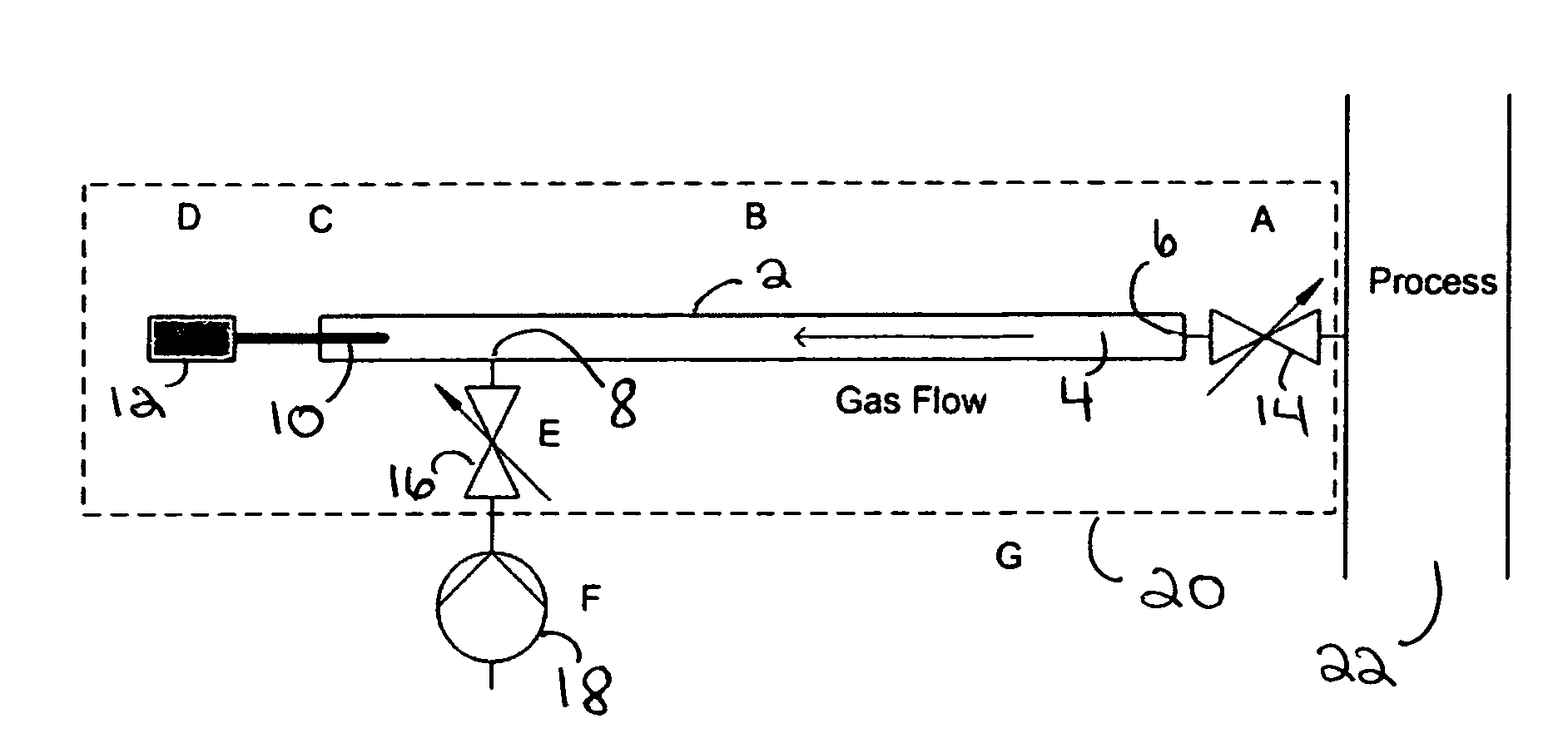
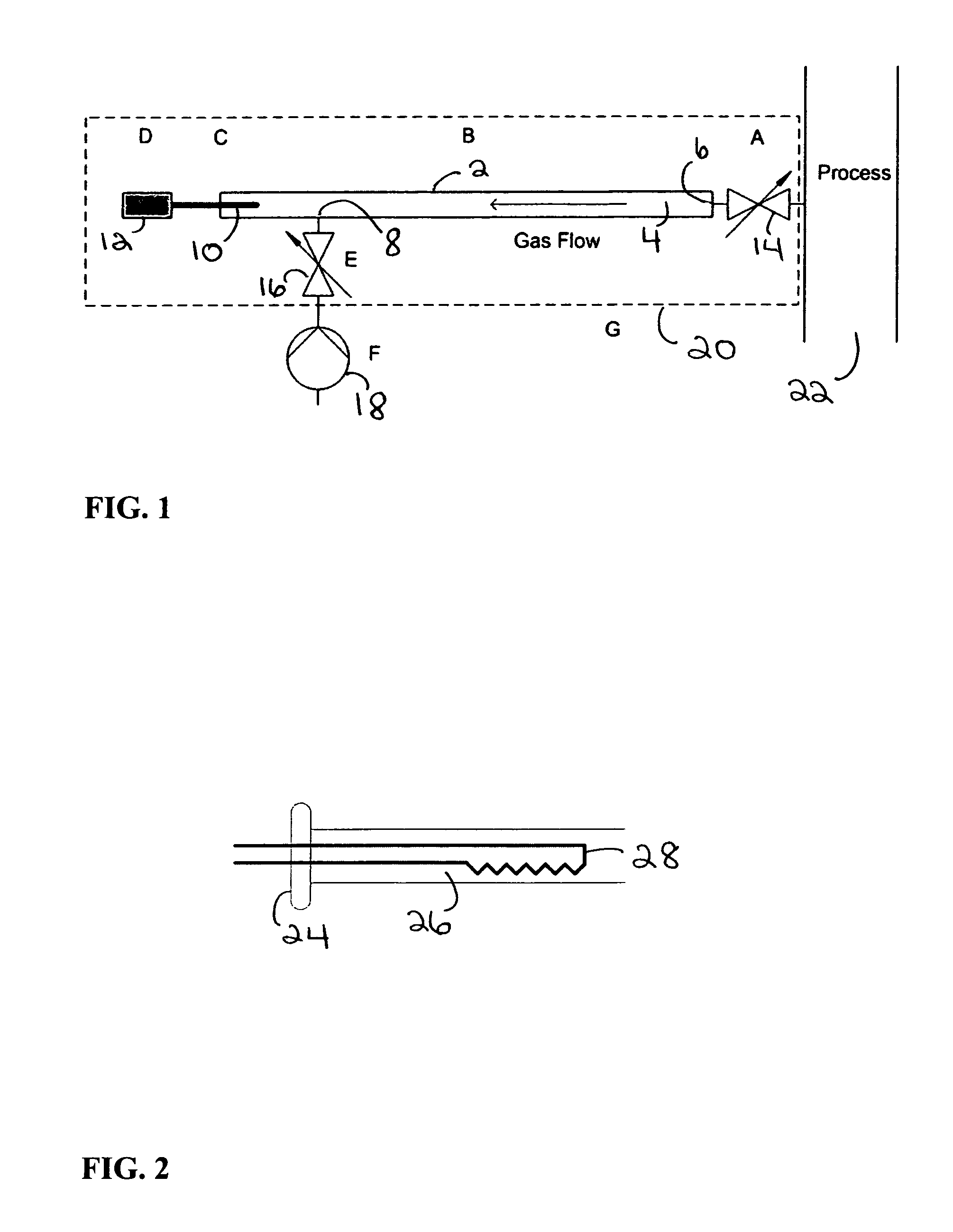
[0042]A gas sensor according to the present invention was constructed using a 0.25 inch O.D. stainless steel tube approximately 1 meter long, with Swagelok (Swagelok Company, Solon, Ohio, USA) or equivalent pressure fittings for the thermal conductivity sensing element, aperture valve, and vacuum valve connections. A tungsten-rhenium filament from GOW-MAC Instrument Co. (Bethlehem, Pa., USA) was employed as the thermal conductivity sensing element. Such a filament has a positive temperature coefficient that is linear along the temperature range from room temperature to 800° C. The filament was connected to the stainless steel tube by means of a pressure seal in an arrangement similar to that shown in FIG. 2. A Wheatstone bridge circuit was connected to the filament to monitor voltage changes in response to changes in filament resistance. The sensor block was maintained at 250° C. during sample measurements, a temperature that maintains water vapor and other condensable components in...

example 2

Measurement of Thermal Conductivity

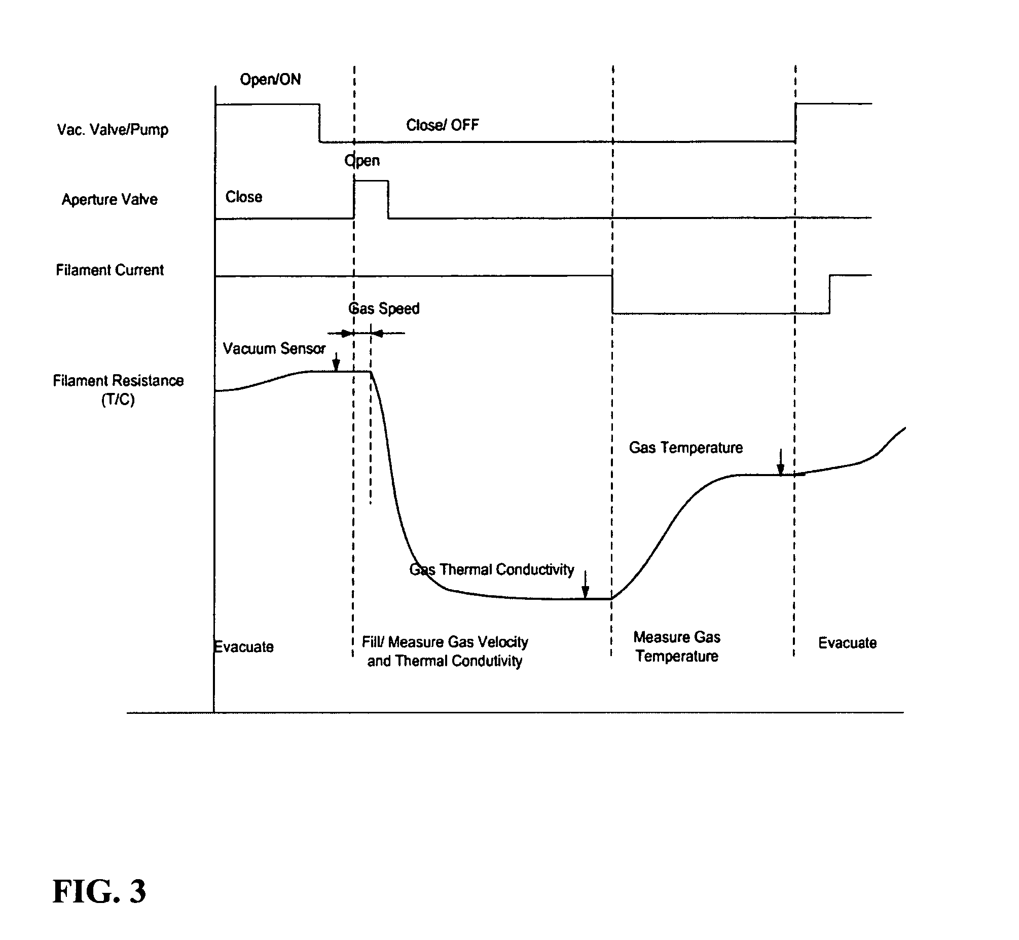
[0043]For a gas sensor constructed as in Example 1, the measurement of thermal conductivity relies on the fact that, when the current level through the metal filament is raised to or above the self-heating point of the filament, the resistance of the filament changes in proportion to the thermal conductivity of a gas sample that surrounds it. The equation defining the relationship between the thermal conductivity of the surrounding gas and the resistance of the filament is:

[0044]q=i2⁢rJ(1)

where q=rate of heat loss, i=current, r=resistance, and J=joules equivalent (4.19 w / cal). Referring to FIG. 5, when a metal filament 48 and a reference filament 50 are connected to a Wheatstone bridge circuit, and a constant-current source (i) applied, small changes in the filament resistance cause bridge voltage changes that can be accurately measured.

[0045]At the start of each measurement cycle, a vacuum pump can be used to lower the pressure in the sample chamb...

example 3

Measurement of Temperature

[0046]For a gas sensor constructed as in Example 1, the resistance of the filament is a direct indication of the absolute temperature of the surrounding gas when the current level of the filament is lowered to below the self-heating level of the filament. The electrical resistance of a filament at any temperature may be calculated by the following equation:

RT=Rr[1+α(T−Tr)]  (2)

where RT=conductor resistance at temperature T, Rr=conductor resistance at reference temperature Tr, and α=temperature coefficient of resistance at the reference temperature Tr

[0047]A gas sensor was constructed according to Example 1. The α value of the tungsten-rhenium filament was 0.00392 Ω / cm-K (Tr=20° C.), and Rr was 31.2 Ω. FIG. 7 shows a calibration curve for the filament of the gas sensor.


PUM


Abstract

An apparatus and method for gas detection. The apparatus comprises a) a sample chamber for holding a gas sample, b) a sealable vacuum port in fluid communication with the sample chamber, for evacuating the sample chamber, c) a sealable inlet port in fluid communication with the sample chamber, for introducing the gas sample into the evacuated sample chamber, and d) a thermal conductivity sensing element at least partly disposed within the sample chamber, for measuring the thermal conductivity of the gas sample. A gas sample released into the evacuated sample chamber requires a time interval to contact the thermal conductivity sensing element. The time interval is a measure of gas speed. Thermal conductivity and temperature of the gas sample are measured following determination of gas speed. By determining three parameters in a single sample of gas, different gas mixtures having similar thermal conductivities can be distinguished.

Description

BACKGROUND[0001]1. Field of Invention[0002]This invention relates generally to gas sensors and methods of detecting gases.[0003]2. Related Art[0004]Gas detection methods based on the thermal conductivity transport property have been widely used because such methods do not show significant selectivity toward a specific gas. Thermal conductivity is defined as the rate at which heat flows through an area of a body or material. Since thermal conductivity is a bulk property of gases, methods based on this property are considered to be near universal or non-specific gas detection methods.[0005]Typically, the thermal conductivity of a gas is measured by heating a resistance element such as a hot wire filament or a thermistor, and contacting the heated element with a gas sample. The temperature of the resistance element is determined by the thermal conductivity of the gas sample, with a change in temperature reflected as a change in resistance of the resistance element. In this method, the ...

Claims


Application Information

Patent Timeline
Patent Type & Authority Patents(United States)
IPC IPC(8): G01F1/68
CPCG01P5/12G01N33/005G01N25/18G01N1/24
Inventor NORBECK, JOSEPH N.PARK, CHAN SEUNGMC CLANAHAN, MICHAELHACKETT, LEGAL REPRESENTATIVE, NORAHACKETT, COLIN E.
Owner RGT UNIV OF CALIFORNIA
Why Eureka
Try Eureka