
Ink jet printing apparatus, ink jet printing method, information processing device and program

a technology of ink jet printing and printing head, which is applied in the direction of printing, other printing apparatus, etc., can solve the problems of inability to meet the market demand for an improved printing speed, the general line type printing apparatus cannot achieve the maximum printing speed, and the proper image printing cannot be continued, so as to improve the output of the printing apparatus and keep the replacement frequency of the print head low

Inactive Publication Date: 2008-07-15
COPYER
View PDF3 Cites 5 Cited by
  • Summary
  • Abstract
  • Description
  • Claims
  • Application Information

AI Technical Summary

Benefits of technology

This solution allows for uninterrupted printing operations by utilizing functional line heads, maintaining high throughput and preventing wasteful paper consumption, while minimizing the concentration of usage on individual print heads, thus extending their lifespan and reducing replacement needs.

Problems solved by technology

In other words, the general ink jet printing apparatus cannot realize a printing speed in excess of the maximum drive frequency of a single line head (a maximum nominal frequency at which ink can be repetitively ejected in one second while keeping a stable image quality).
Therefore, the general line type printing apparatus has a problem of being unable to meet the market demand for an improved printing speed.
The high-speed line type ink jet printing apparatus, however, has a problem that, should any one of a plurality of line heads ejecting the same color ink deteriorate in the ink ejection performance, a proper image printing cannot be continued.
The degree of performance degradation is not uniform among a plurality of line heads and only one of the line heads often reaches the end of its service life early.
When a sub ink tank is provided for each line head, inks in the sub tanks are not necessarily consumed uniformly.
In the event of an ink ejection failure, the continued printing operation will deteriorate the print quality.
That is, continuing the printing operation and maintenance of the print quality may contradict each other.
However, there are many difficulties that need to be overcome before such countermeasures can be realized because prolonging the service life of the line heads requires a lot of time and cost for research and development and increasing the sub tank capacity will result in an increase in the overall size of the printing apparatus and a cost increase.
In this case, if the raster data that was generated by rasterizing the image data is divided and allocated to a plurality of line heads for printing, a problem may occur in which only a particular line head is used concentratedly and the replacement frequency of that line head increases.

Method used


Image

  • Ink jet printing apparatus, ink jet printing method, information processing device and program
  • Ink jet printing apparatus, ink jet printing method, information processing device and program
  • Ink jet printing apparatus, ink jet printing method, information processing device and program

Examples


first embodiment

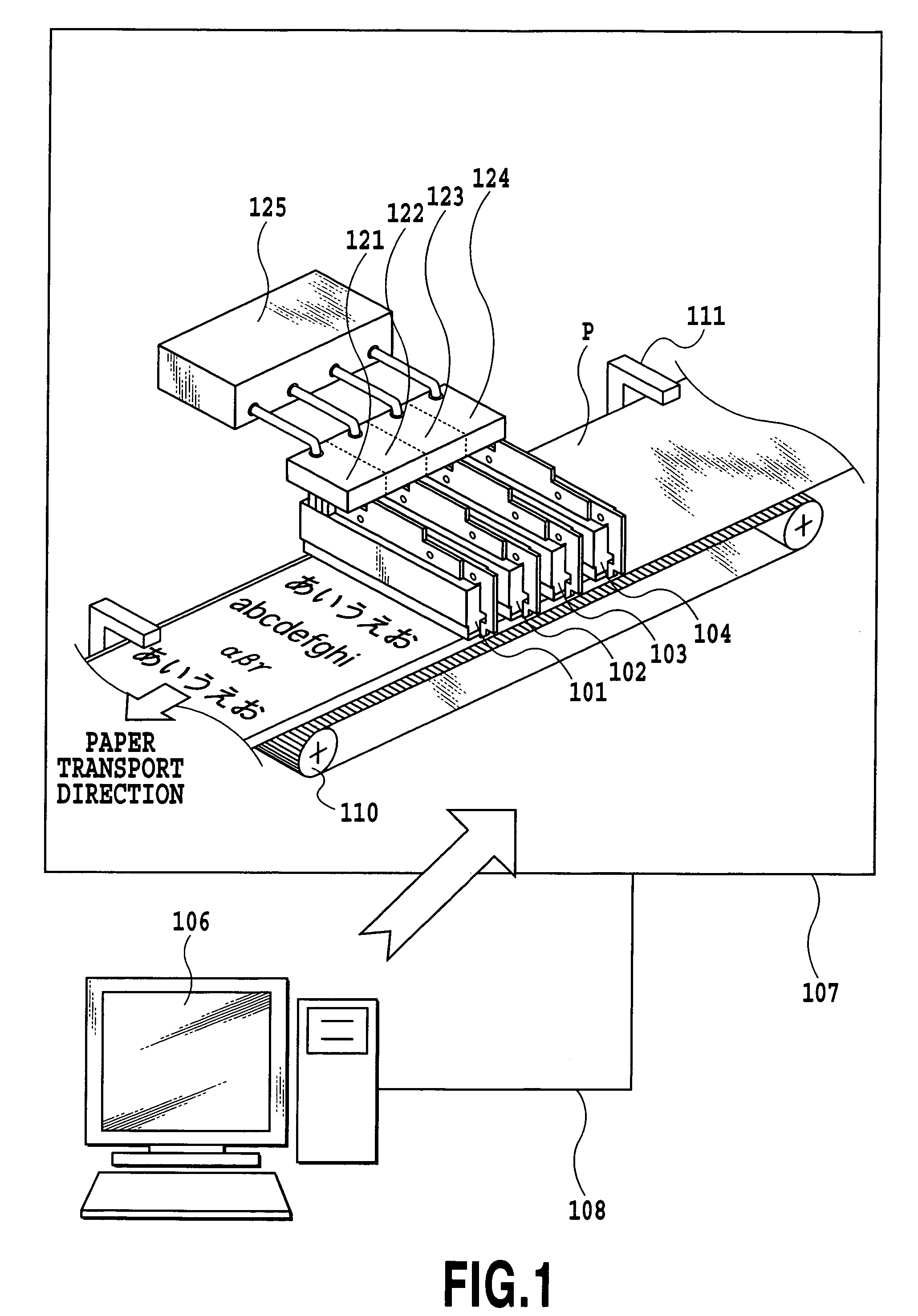
[0044]FIG. 1 illustrates a main configuration of the ink jet printing system in the embodiment of this invention.

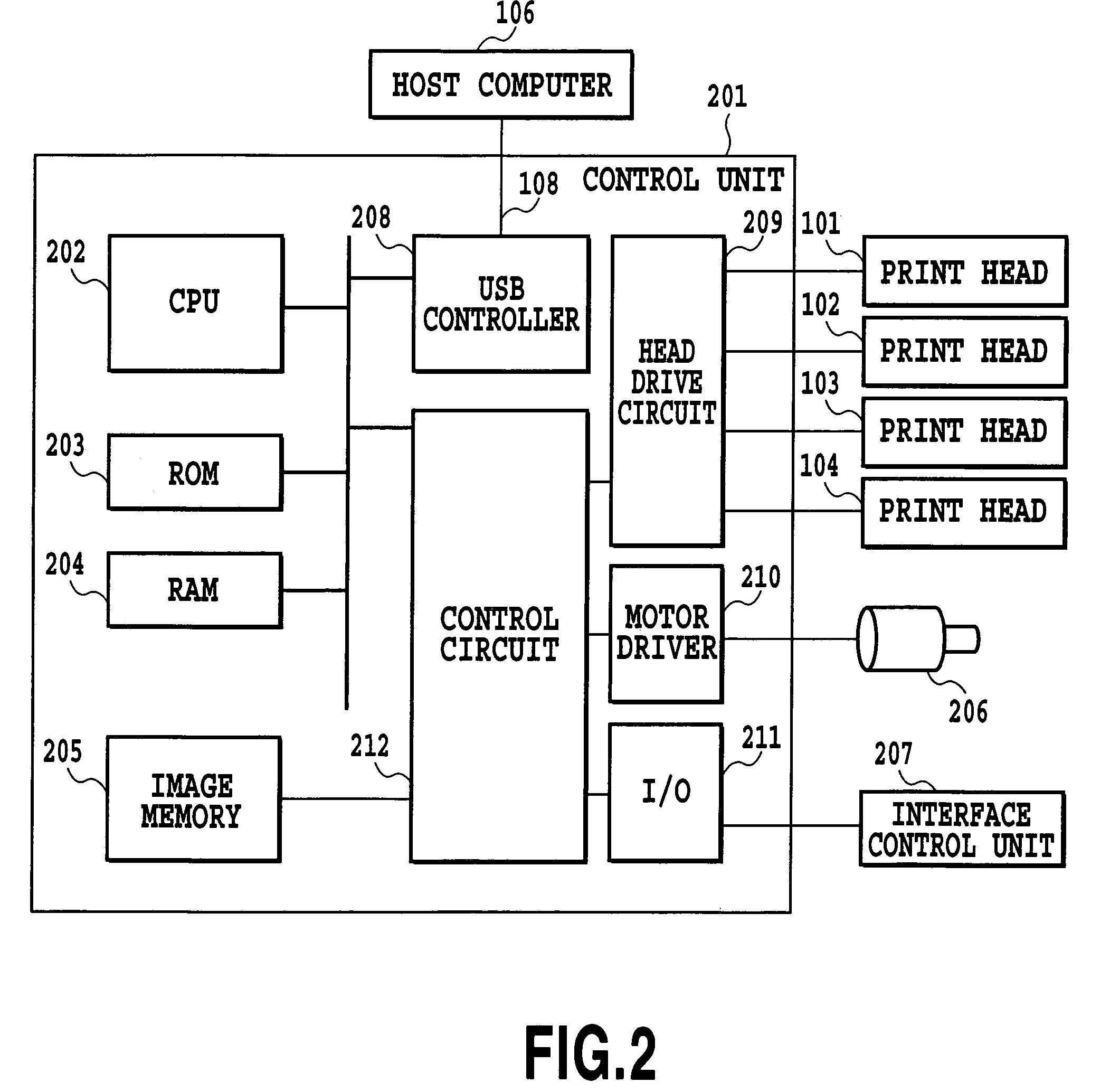
[0045]The ink jet printing system of this embodiment comprises an ink jet printing apparatus 107 that performs a printing operation on a print medium, and a host computer 106 that sends and receives a variety of data to and from the ink jet printing apparatus 107. The host computer 106 and the ink jet printing apparatus 107 are connected through a printer cable 108. Various data including image data and a cleaning command processed by the host computer 106 are transmitted to the ink jet printing apparatus 107 which, according to these data, performs printing. A printer status of the ink jet printing apparatus 107, such as error data, is sent to the host computer 106 so that the host computer can recognize the condition of the ink jet printing apparatus.

[0046]The ink jet printing apparatus of this embodiment forms a monochrome image using four elongate line heads that ejec...

second embodiment

[0079]Next, a second embodiment of this invention will be described by referring to FIG. 8 through FIG. 10.

[0080]This second embodiment also has the same construction of FIG. 1 and FIG. 2 as in the first embodiment. The following explanation, therefore, mainly concerns an image forming operation executed by the second embodiment of the ink jet printing apparatus 107.

[0081]The ink jet printing apparatus of the second embodiment is characterized by the fact that, in dividing raster data, which is obtained by rasterizing the image data of one color, into a plurality of images of the same color and allocating the divided raster data to a plurality of print heads, the method of allocating the divided raster data is changed in units of pages. This is explained in detail by referring to FIG. 7.

[0082]In FIG. 7, denoted 400 is raster data produced by rasterizing the image data to be printed on each page of the print medium P. 400A (8 dots), 400B (2 dots), 400C (2 dots), 400D (2 dots), 400E (...

third embodiment

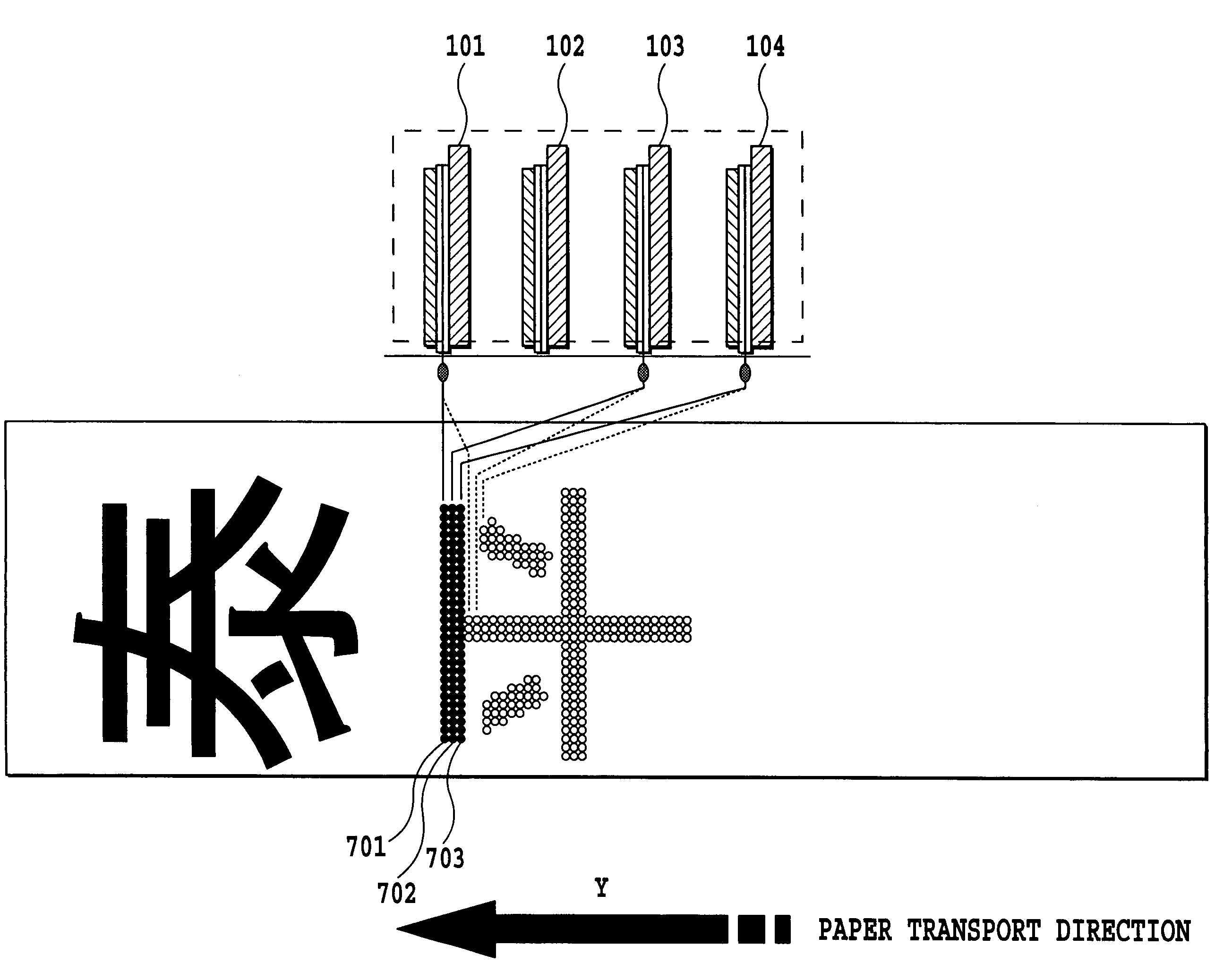
[0092]In the above second embodiment, the line heads to which the divided raster data is allocated are changed every page to avoid any particular line head being used excessively. The third embodiment is characterized by the fact that, in dividing the raster data, which is generated by rasterizing the same image data of one color, into a plurality of images of the same color and allocating the divided raster data to a plurality of line heads, the line heads to be allocated with the raster data are changed according to the number of pixels printed by each line head. Now, a divided image forming means, that determines the destination print head of the divided raster data according to the number of pixels printed by each line head, will be explained by referring to FIG. 8.

[0093]In FIG. 8, denoted 500 is raster data generated by rasterizing the image data. 500A (1 dot), 500B (2 dots), 500C (3 dots) and 500D (4 dots) are divided raster data.

[0094]Processing on the first page allocates th...


PUM


Abstract

An ink jet printing apparatus having excellent throughput can continue a printing operation without interruption if one or more line heads falls into an unprintable state when the apparatus is printing images of the same color using a plurality of line heads. For this purpose, image data for images of the same color is divided and the divided image data is supplied to such a line head of the plurality of line heads intended to form images of the same color that is capable of ejecting ink properly, so that the ink ejectable line head performs the printing operation according to the supplied image data.

Description

[0001]This application claims priority from Japanese Patent Application Nos. 2004-290558 filed Oct. 1, 2004 and 2004-309816 filed Oct. 25, 2004, which are hereby incorporated by reference herein.BACKGROUND OF THE INVENTION[0002]1. Field of the Invention[0003]The present invention relates to an ink jet printing apparatus, a printing method, a print medium and a program. More particularly, this invention relates to an ink jet printing apparatus, a printing method, a print medium and a program for forming an image on a print medium by dividing an image of one color into a plurality of images of the same color and printing the divided images as the print medium is transported using a plurality of line heads arranged along a transport direction of the print medium.[0004]2. Description of the Related Art[0005]In repetitively printing fixed images, such as business forms, in large volumes, a dry electrophotographic printer has been used. In recent years, an ink jet printing apparatus has c...

Claims


Application Information

Patent Timeline
Patent Type & Authority Patents(United States)
IPC IPC(8): B41J2/155
CPCB41J2/17546
Inventor MOROOKA, YOSHINORISHINO, YOSHIYUKI
Owner COPYER
Learn More