Minimally-invasive heart valve with cusp positioners

a heart valve and cusp positioner technology, applied in the field of medical implants, can solve the problems of insufficient prior art mis valves, no information about the structure of the valve itself, and a long recovery period, and achieve the effect of convenient implantation, high adaptability and simple us

Active Publication Date: 2008-07-15
EDWARDS LIFESCIENCES CORP
View PDF113 Cites 435 Cited by
  • Summary
  • Abstract
  • Description
  • Claims
  • Application Information

AI Technical Summary

Benefits of technology

[0014]The present invention provides improved prosthetic heart valves that can be implanted in a minimally-invasive manner, but which also has aspects that make it useful for conventional surgeries. The valves and implant tools and methods described herein provide a highly adaptive and simple to use endovascular delivery option for cardiac surgeons or cardiologists because of features that facilitate implantation. The valve is designed to be expelled from a delivery tube in an implant area and then expanded and / or positioned to contact the surrounding tissue without additional anchoring structures. Further, the valve and implant tools permit repositioning and even recollapse of the valve if needed.

Problems solved by technology

Such open heart surgery is particularly invasive and involves a lengthy and difficult recovery period.
Although these and other such devices provide various ways for collapsing, delivering, and then expanding a “heart valve” per se, none of them disclose much structural detail of the valve itself.
All of the prior art MIS valves are inadequate in this regard.
Furthermore, use of conventional support stents or wireforms is difficult in MIS valves because of the need to compress the valve into a relatively small diameter delivery package, which creates material challenges.
Sometimes the natural leaflets are heavily calcified, and their removal entails some risk of plaque particles being released into the bloodstream.
The relatively uneven surface of the calcified annulus and leaflets creates sizing problems and may complicate the delivery and placement steps.

Method used


Image

  • Minimally-invasive heart valve with cusp positioners
  • Minimally-invasive heart valve with cusp positioners
  • Minimally-invasive heart valve with cusp positioners

Examples


Embodiment Construction

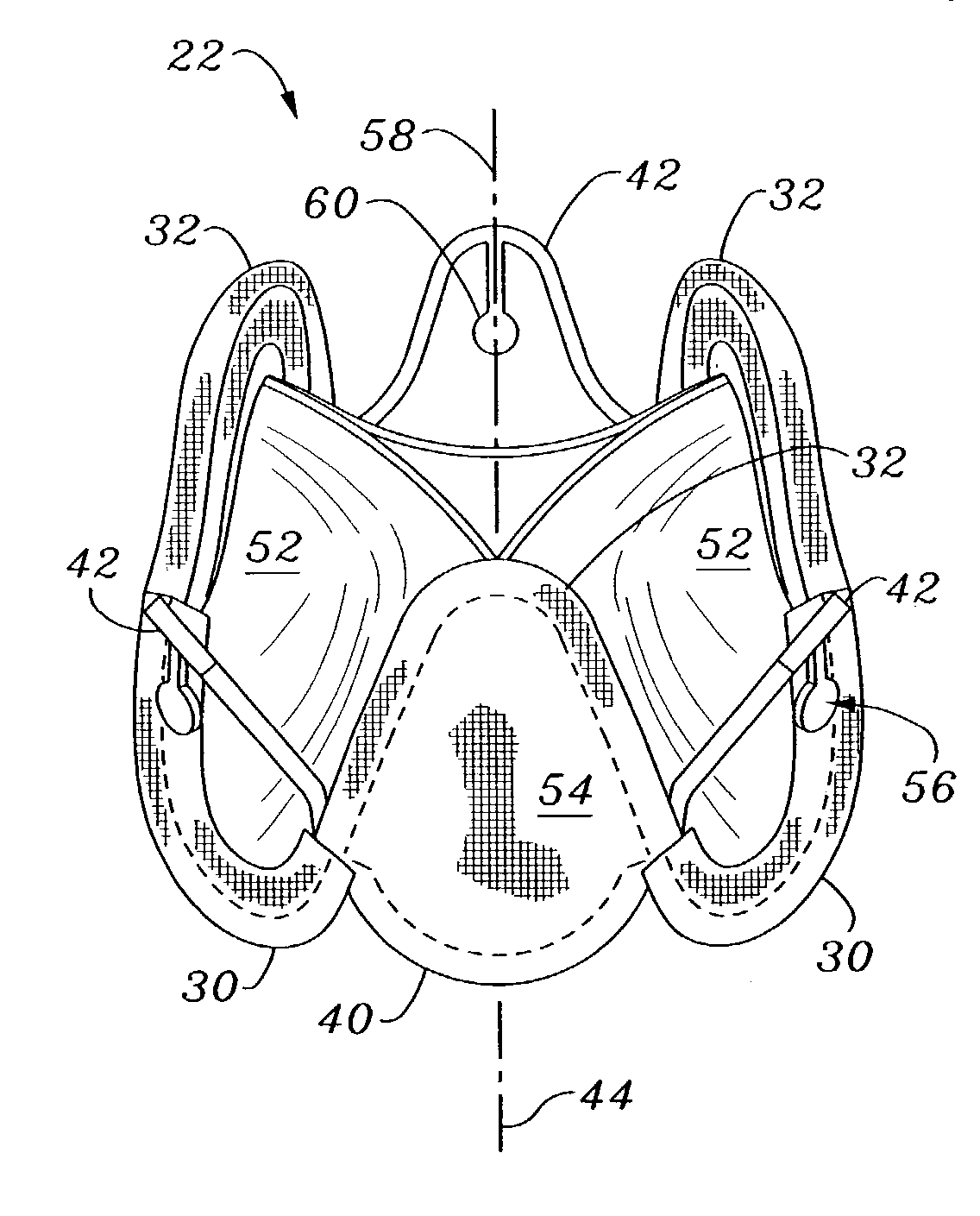
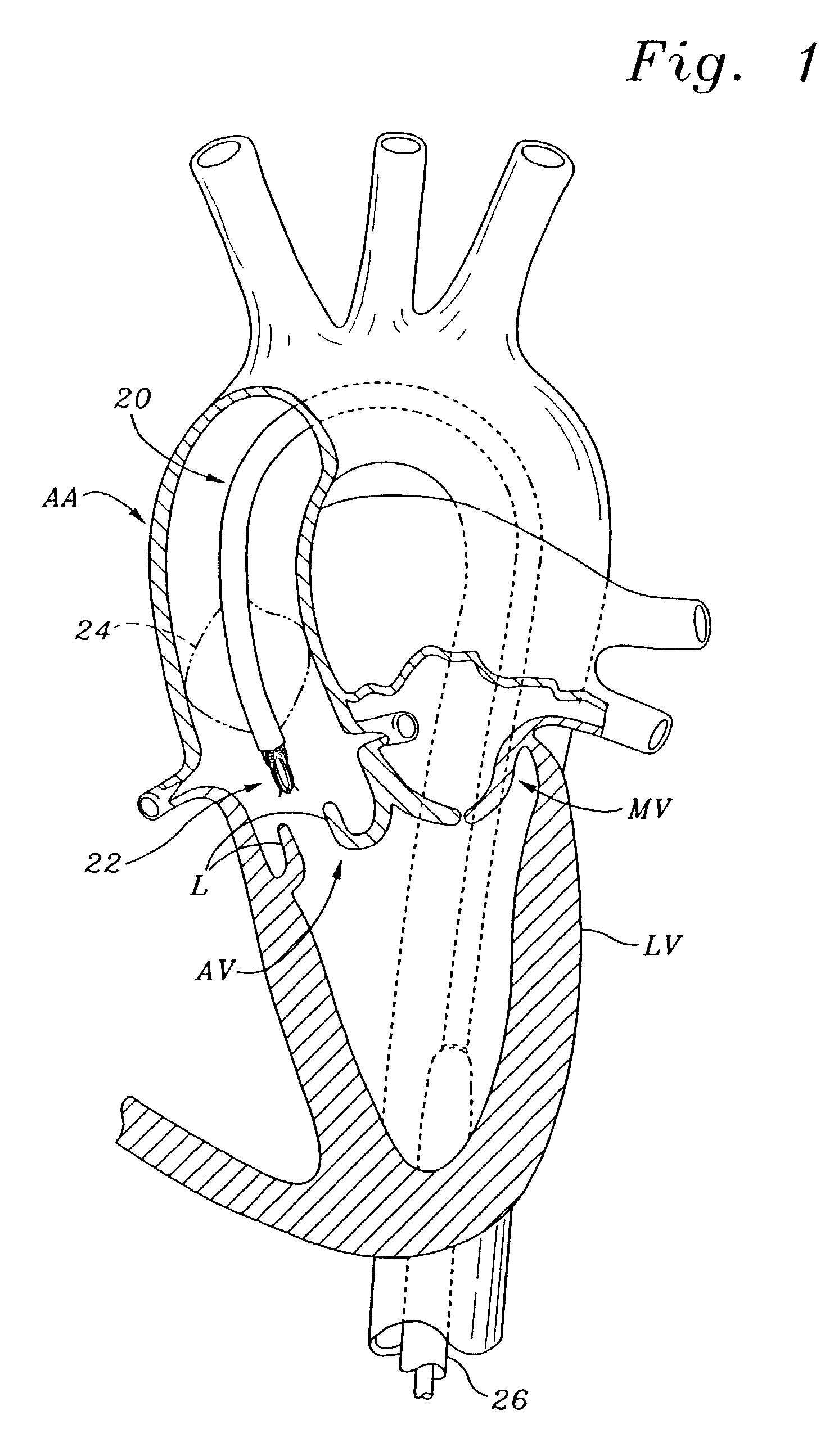
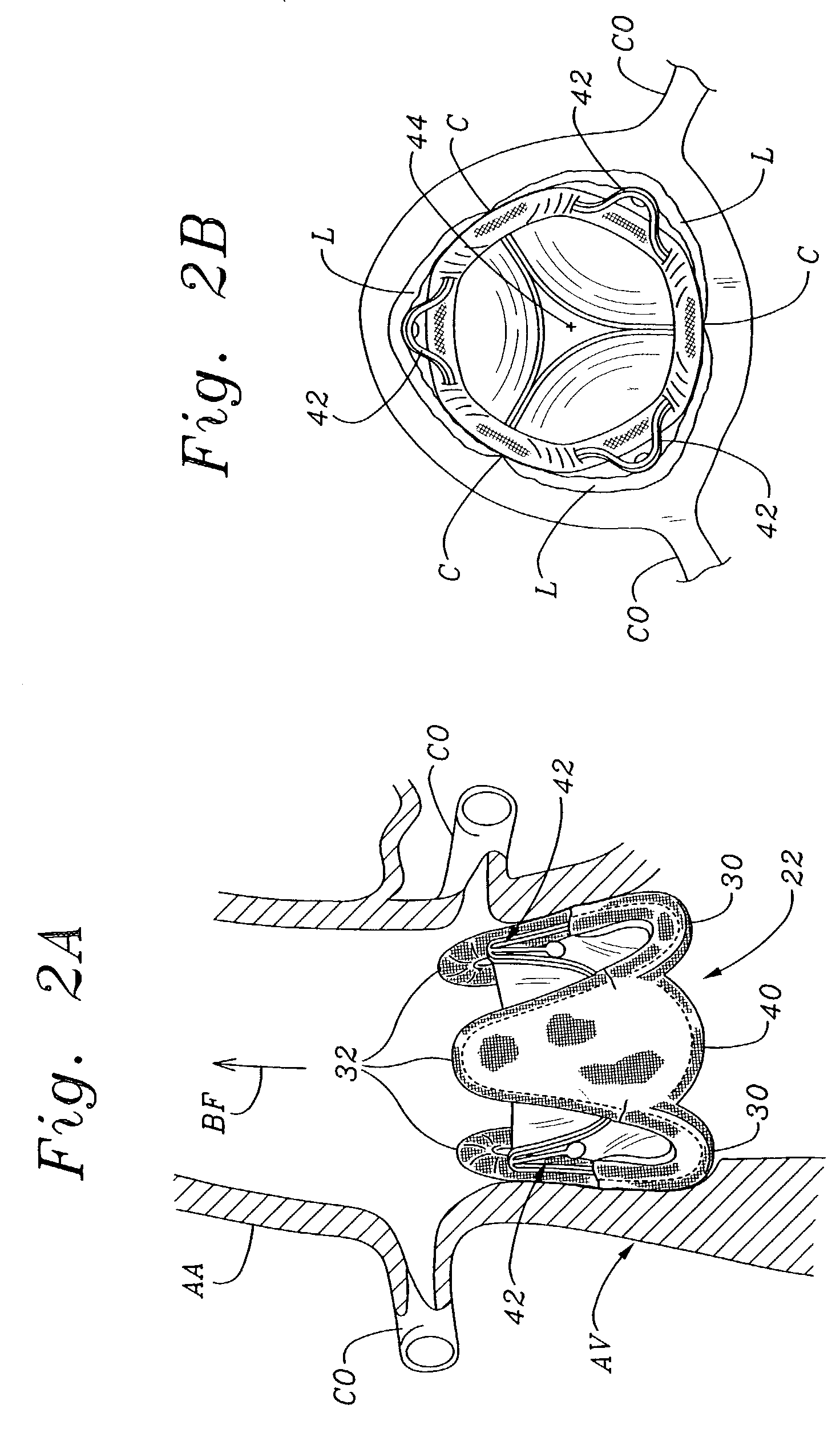
[0056]The present invention provides an improved minimally invasive (MIS) valve support frame, MIS valve, and methods of construction and delivery as described herein and shown in the accompanying drawings.

[0057]The invention pertains primarily to flexible leaflet heart valves and internal support frames, which are also referred to in the art as stents or wireforms. As mentioned above, the flexible leaflets can be formed from biological (e.g., bovine pericardium) or synthetic material. In this context, a “support frame” for a flexible leaflet heart valve provides the primary internal structural support for the leaflets, and substantially mimics the natural fibrous skeleton of the respective valve annulus. More specifically, each of the leaflets has an outer edge that is coupled to a portion of the support frame such that its inner edge is free to move within the orifice area of the valve, thus providing the opening and closing surfaces thereof. A biological xenograft valve can be us...


PUM


Abstract

A prosthetic heart valve having an internal support frame with a continuous, undulating leaflet frame defined therein. The leaflet frame has three cusp regions positioned at an inflow end intermediate three commissure regions positioned at an outflow end thereof. The leaflet frame may be cloth covered and flexible leaflets attached thereto form occluding surfaces of the valve. The support frame further includes three cusp positioners rigidly fixed with respect to the leaflet frame and located at the outflow end of the support frame intermediate each pair of adjacent commissure regions. The valve is desirably compressible so as to be delivered in a minimally invasive manner through a catheter to the site of implantation. Upon expulsion from catheter, the valve expands into contact with the surrounding native valve annulus and is anchored in place without the use of sutures. In the aortic valve position, the cusp positioners angle outward into contact with the sinus cavities, and compress the native leaflets if they are not excised, or the aortic wall if they are. The support frame may be formed from a flat sheet of Nitinol that is bent into a three-dimensional configuration and heat set. A holder having spring-like arms connected to inflow projections of the valve may be used to deliver, reposition and re-collapse the valve, if necessary.

Description

FIELD OF THE INVENTION[0001]The present invention relates generally to medical implants, and more particularly to minimally-invasive or collapsible / expandable heart valves and methods of delivering and implanting such valves.BACKGROUND OF THE INVENTION[0002]Prosthetic heart valves are used to replace damaged or diseased heart valves. In vertebrate animals, the heart is a hollow muscular organ having four pumping chambers: the left and right atria and the left and right ventricles, each provided with its own one-way valve. The natural heart valves are identified as the aortic, mitral (or bicuspid), tricuspid and pulmonary valves. Prosthetic heart valves can be used to replace any of these naturally occurring valves, although repair or replacement of the aortic or mitral valves is most common because they reside in the left side of the heart where pressures are the greatest.[0003]Where replacement of a heart valve is indicated, the dysfunctional valve is typically cut out and replaced...

Claims


Application Information

Patent Timeline
Patent Type & Authority Patents(United States)
IPC IPC(8): A61F2/24A61B17/22
CPCA61F2/2418A61F2/2436A61F2/2412A61F2/2427A61B17/221A61F2002/9522A61F2220/0075A61F2220/0016A61F2220/0066A61F2/9525A61F2/9522A61F2/243
Inventor IOBBI, MARIO M.
Owner EDWARDS LIFESCIENCES CORP
Why Eureka
Try Eureka