
Supersonic vapor compression and heat rejection cycle

a supersonic and heat rejection cycle technology, applied in the direction of lighting, heating apparatus, fluid pressure control, etc., can solve the problems of inconvenient operation of the fuel cell cooling system, and inability to meet the requirements of the application. achieve the effect of improving the overall efficiency of the fuel cell system, reducing pumping power, and improving control over the stack operating temperatur

Active Publication Date: 2008-07-15
GM GLOBAL TECH OPERATIONS LLC
View PDF8 Cites 20 Cited by
  • Summary
  • Abstract
  • Description
  • Claims
  • Application Information

AI Technical Summary

Benefits of technology

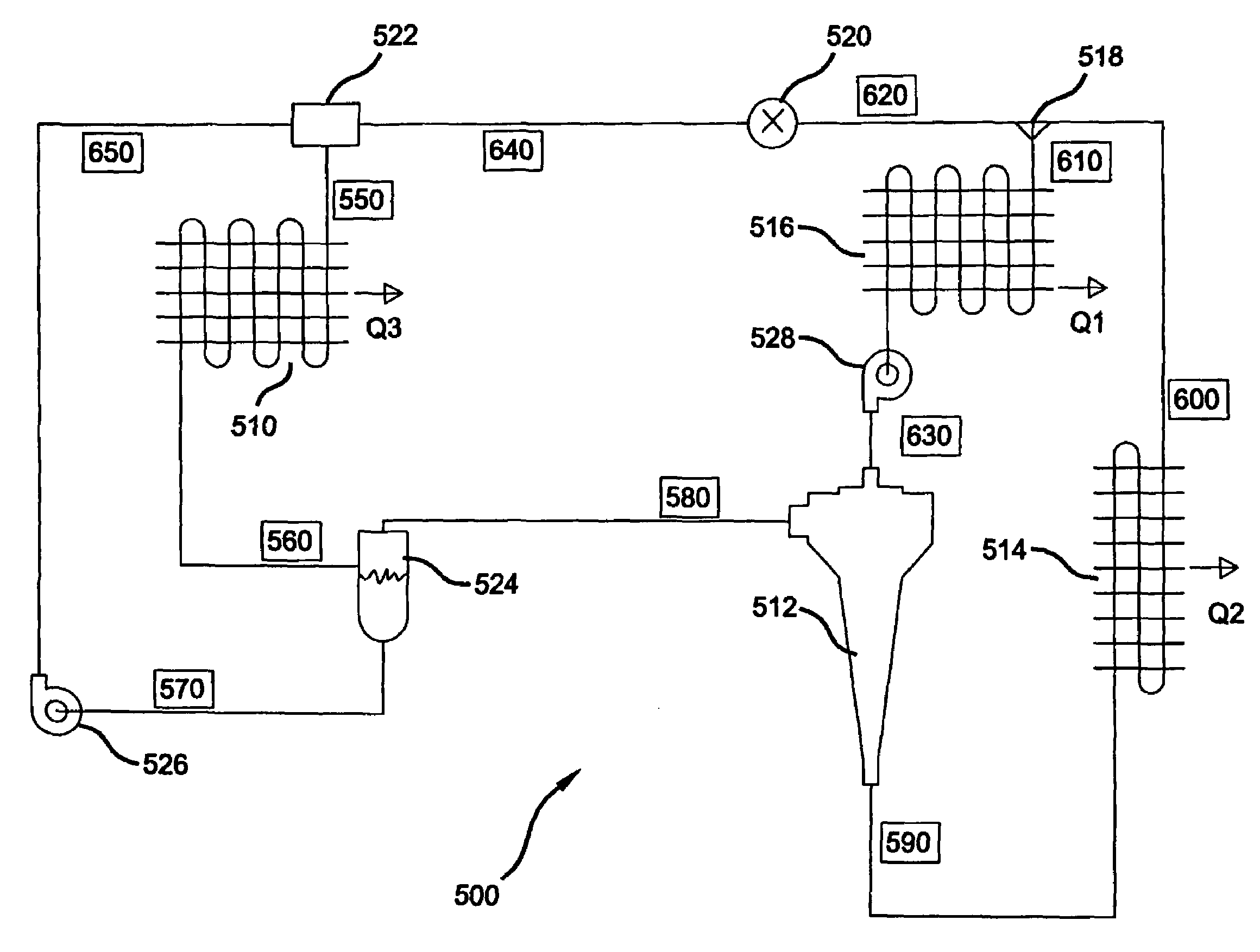
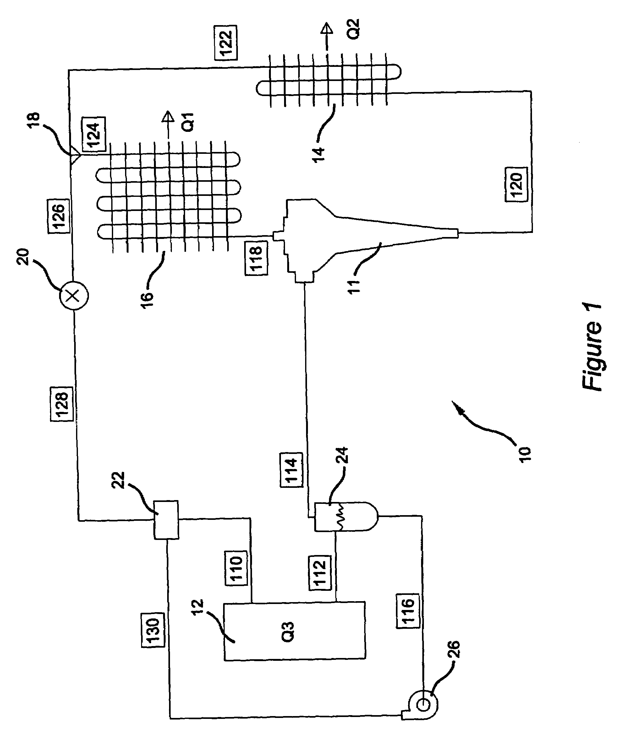
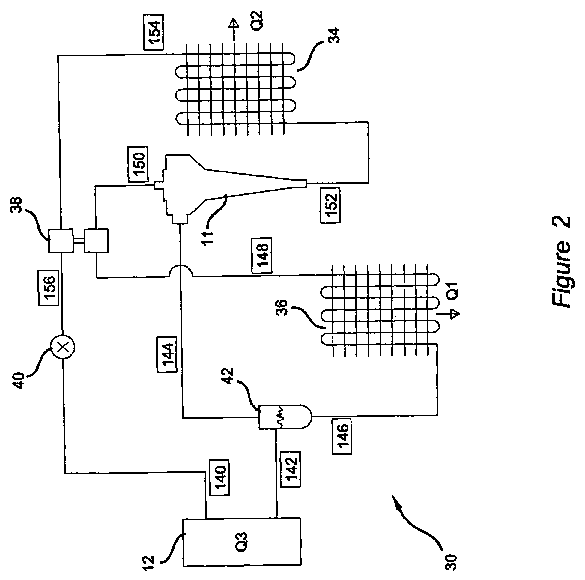
The present invention is about a method and apparatus for extracting waste heat from a heat source and rejecting it to the environment through a heat exchanger. The invention uses vapor cooling of the heat source to control its operating temperature and improve its efficiency. The high temperature, high pressure coolant is delivered to the heat exchanger and then circulated to the inlet of the fuel cell stack. This eliminates the need for a large circulation pump and increases the overall efficiency of the fuel cell system. The invention can be used in various systems where heat transfer occurs and aims to decrease pumping power and increase the temperature at which heat is rejected.

Problems solved by technology

The catalytic particles are typically costly precious metal particles.
As such these MEAs are relatively expensive to manufacture and require certain conditions, including proper water management and humidification and control of catalyst fouling constituents such as carbon monoxide (CO), for effective operation.
Current fuel cell cooling systems are undesirably large, including the large circulation pump for circulating the liquid coolant through the fuel cell stack (i.e. heat source) to the heat exchanger where the waste thermal energy (i.e., heat) is transferred to the environment.
As is well known, the expense associated with large heat exchangers and the other cooling system components (recirculation pump, proportional mixing valves, PID controllers, etc.), combined with packaging constraints caused by physical size requirements of the components, have had a detrimental impact on widespread commercialization of fuel cell systems.

Method used


Image

  • Supersonic vapor compression and heat rejection cycle
  • Supersonic vapor compression and heat rejection cycle
  • Supersonic vapor compression and heat rejection cycle

Examples


first embodiment

[0035]Referring now to FIG. 4, nozzle / ejector, unit 11 is shown in section to include a valve body 200 and a nozzle block 202 mounted in valve body 200. Valve body 200 is a hollow cylindrical structure which defines a nozzle section 204, a converging ejector section 206, and a discharge section 208. An annular vapor inlet chamber 210 is defined between a portion of nozzle block 202 and a valve body 200. The subsonic vapor inlet stream flowing from the discharge side of the fuel cell stack is delivered to inlet chamber 210 through one or more vapor inlet ports 212. Likewise, the subsonic liquid inlet stream is delivered through a central liquid inlet port 216 to one end of a long liquid flow passage 214 formed in nozzle block 202.

[0036]Nozzle section 204 of valve body 200 defines an annular vapor nozzle 218 defined by a restricted throat area formed between a convergent / divergent inner wall surface of valve body 200 and a frusto-conical outer wall surface of nozzle block 202. An expa...

second embodiment

[0039]Referring now to FIG. 5, supersonic nozzle / ejector unit 11 is shown to include a hollow cylindrical valve body 300 and a nozzle tube 302 disposed within valve body 300. Valve body 300 defines an inlet nozzle section 304, an ejector section 306, and a discharge section 308. An annular vapor inlet chamber 310 is defined between valve body 300 and nozzle tube 302 and is adapted to receive the subsonic vapor inlet stream. Likewise, the subsonic liquid inlet stream is delivered through an elongated flow passage 314 formed in nozzle tube 302. Nozzle section 304 of valve body 300 defines an annular vapor nozzle 318 that is formed between a convergent / divergent section of valve body 300 and nozzle tube 302. An expansion chamber 320 is located downstream of vapor nozzle 318 and upstream of a liquid nozzle 322 formed at the terminal end of liquid flow passage 314. In addition, an acceleration chamber 324 is formed between nozzle tube 302 and a bulbous portion 325 of ejector section 306....


PUM

PropertyMeasurementUnit
operating temperatureaaaaaaaaaa
mass flow rateaaaaaaaaaa
temperatureaaaaaaaaaa

Abstract

Method and apparatus for cooling a fuel cell stack. The cooling system uses vaporization cooling of the fuel stack and supersonic vapor compression of the vaporized coolant to significantly increase the temperature and pressure of the liquid coolant flowing through a heat exchanger. By increasing the heat rejection temperature of the coolant delivered to the heat exchanger, the heat transfer area of the heat exchanger can be reduced and the mass flow rate of coolant can also be reduced. The increased fluid pressure is used to circulate the coolant through the cooling system, thereby eliminating the circulation pump associated with conventional systems.

Description

CROSS-REFERENCE TO RELATED APPLICATIONS[0001]This application is a divisional of U.S. patent application Ser. No. 10 / 191,201, filed Jul. 9, 2002, now U.S. Pat. No. 6,835,484, which issued on Dec. 28, 2004, The disclosure of the above application is incorporated herein by reference.FIELD OF THE INVENTION[0002]The present invention relates generally to a method and apparatus for transferring heat, and more specifically, for cooling a fuel cell stack.BACKGROUND OF THE INVENTION[0003]Cooling systems are implemented in a variety of applications for cooling a heat source. Generally, cooling systems include a cooling fluid flowing therethrough, which undergoes phase changes to perform the cooling function. In particular, the cooling fluid cools the heat source via a heat transfer therefrom, whereby the cooling fluid is caused to vaporize from an original liquid form. The coolant fluid, in vapor form flows through a heat exchanger which is in heat exchange communication with a lower tempera...

Claims


Application Information

Patent Timeline
Patent Type & Authority Patents(United States)
IPC IPC(8): H01M8/04F28F7/00F25B1/06H01M8/02
CPCF25B1/06H01M8/04074H01M8/04029Y02E60/50
Inventor FLY, GERALD A
Owner GM GLOBAL TECH OPERATIONS LLC
Learn More