
Method of detecting an analyte in a fluid

a fluid and analyte technology, applied in the field of detection, can solve the problems of destroying the integrity of the holographic support medium, limiting the industrial application of the sensor, and hysteresis

Inactive Publication Date: 2008-07-22
SMART HOLOGRAMS
View PDF6 Cites 27 Cited by
  • Summary
  • Abstract
  • Description
  • Claims
  • Application Information

AI Technical Summary

Benefits of technology

"The invention is a method and device for detecting a substance in a fluid by using a holographic element. The element changes its optical properties when the fluid interacts with it, and this interaction is reversible. This allows for continuous detection of the substance in real-time, even if the fluid is static or flowing through the device. The invention can be used in vivo or in vitro, and can provide kinetic measurements and act as a control system. The device includes a holographic element and a window for non-ionizing radiation to observe any reactions that occur in the element."

Problems solved by technology

It concludes that optical response to an increasing and decreasing cycle of humidity shows a hysteresis which limits its industrial application as a sensor.
Trypsin acts on the gelatin medium, irreversibly destroying the integrity of the holographic support medium.

Method used


Image

  • Method of detecting an analyte in a fluid
  • Method of detecting an analyte in a fluid
  • Method of detecting an analyte in a fluid

Examples


example 1

Detection of Glucose

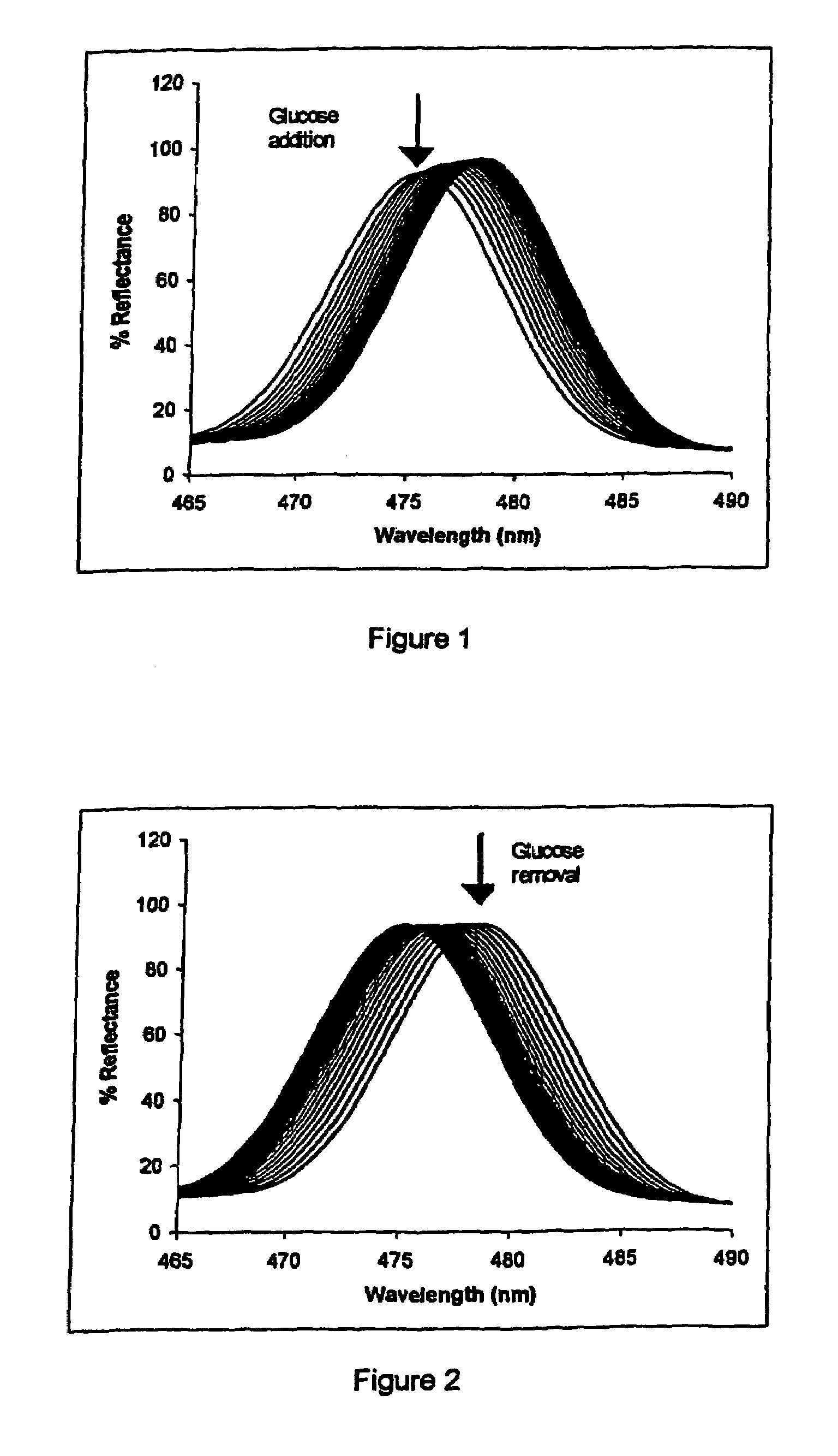
[0041]A monomer mixture of 0.36 g acrylamide, 0.42 g methacrylamide, 0.35 g N,N-dimethylacrylamide, 1 ml water, 40 μl 5% DMPA, 0.03 g methylene bis-acrylamide, and 0.1 g vinylphenylboronic acid was adjusted to pH 9 by addition of aqueous NaOH, and subsequently polymerised. Silver was added to the resulting polymer using 0.2M AgNO3 dissolved in 5% acetic acid. The hologram was then recorded in 20% methanol and developed in a standard developer; such developers are detailed in Practical Holography by Graham Saxby, published by Prentice Hall.

[0042]Detection of glucose was made in the presence of a 0.1 M phosphate buffer with 0.1 M NaCl solution at various pH values. The hologram was placed in 1 ml of buffer with a stirrer, and 20 ml of glucose in water (which had been left for 24 hours) was added to the buffer to a glucose concentration of 2 mM.

[0043]Readings were taken at 30 second intervals for a range of pH values. The system was reversible at all pH values (incl...

example 2

Detection of Oxygen Using “Vaska's Complex”

[0045]“Vaska's complex” was immobilised onto a plain HEMA hologram by evaporation from solution in chloroform (2 ml of 5 mg / ml solution). The hologram was then sparged with oxygen in a nitrogen-saturated buffer (50 mmol phosphate buffer, pH 7.0).

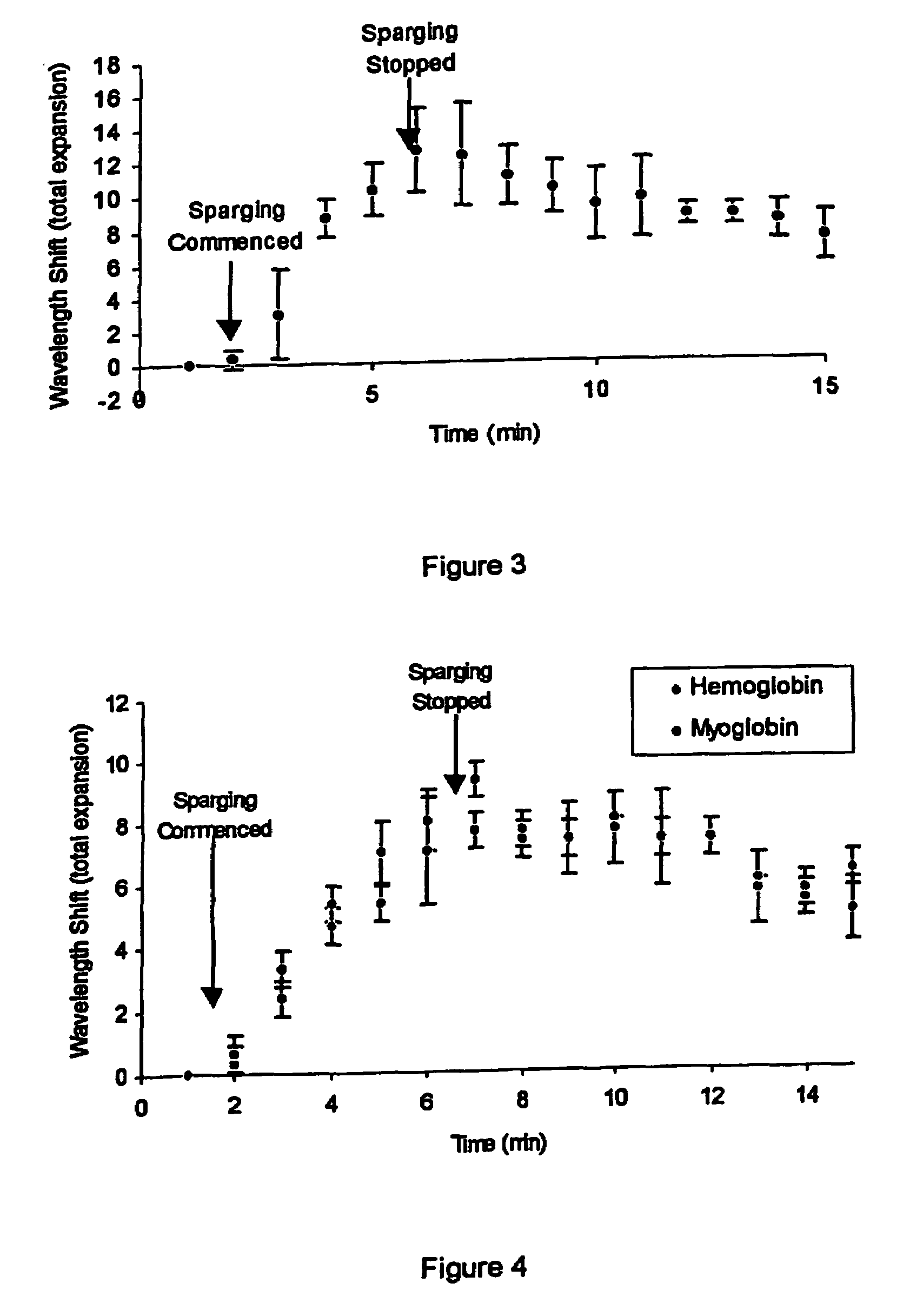
[0046]Upon sparging with oxygen, a small, reversible expansion occurred, resulting in an increase in wavelength of about 10 nm relative to controls. This wavelength shift is shown in FIG. 3. After sparging ceased, a proportion of the bound oxygen molecules underwent the reverse reaction and the holographic medium contracted slightly. This was observed as a slight reduction in wavelength.

example 3

Detection of Oxygen Using Oxygen-binding Proteins

[0047]A holographic sensor was produced by immobilising haemoglobin onto a HEMA polymer by drying, followed by the addition of 1.5% acidified glutaraldehyde for 3 minutes. A holographic sensor comprising immobilised myoglobin was similarly produced.

[0048]The holograms were sparged with oxygen for approximately 5 minutes. As can be seen from FIG. 4, a response to changing oxygen concentration was displayed by both haemoglobin and myoglobin containing holograms.


PUM

PropertyMeasurementUnit
refractive indexaaaaaaaaaa
angleaaaaaaaaaa
angleaaaaaaaaaa

Abstract

A method for the detection of an analyte in a fluid, comprising contacting the fluid with a holographic element comprising a medium and a hologram disposed throughout the volume of the medium, wherein an optical characteristic of the element changes as a result of a variation of a physical property occurring throughout the volume of the medium, wherein the variation arises as a result of interaction between the medium and the analyte, and wherein the reaction and the variation are reversible; and detecting any change of the optical characteristic.

Description

[0001]This application is a National Stage Application of International Application Number PCT / GB03 / 01499, filed Apr. 4, 2003; which claims priority to United Kingdom Application No. 0207944.0, filed Apr. 5, 2002.FIELD OF THE INVENTION[0002]This invention relates to a method of detection based on a sensitive element which is a hologram, and a device for use in such a method.BACKGROUND TO THE INVENTION[0003]A short communication to the International Journal of Optoelectronics 7(3):449-452 (1992), by Spooncer et al, entitled “A humidity sensor using a wavelength-dependent holographic filter with fibre optic links”, describes the response of gelatin-based Bragg reflection holograms to ambient humidity. It concludes that optical response to an increasing and decreasing cycle of humidity shows a hysteresis which limits its industrial application as a sensor.[0004]WO-A-9526499 discloses a holographic sensor, based on a volume hologram. This sensor comprises an analyte-sensitive matrix hav...

Claims


Application Information

Patent Timeline
Patent Type & Authority Patents(United States)
IPC IPC(8): G01N33/543G01N33/483G01N21/05G01N21/47G01N21/77G01N33/50G02B5/32G03H1/04
CPCG01N21/05G01N21/4788G03H1/0248G02B5/32G01N2021/7723Y10S436/805G03H2001/0044Y10S435/808G01N21/47G03H1/02
Inventor LOWE, CHRISTOPHER ROBINDAVIDSON, COLIN ALEXANDER BENNETTBLYTH, JEFFREYKABILAN, SATYAMOORTHYMARSHALL, ALEXANDER JAMESGONZALEZ, BLANCA MADRIGALJAMES, ANTHONY PETER
Owner SMART HOLOGRAMS
Learn More